Magnetic dipole yagi antenna

A Yagi antenna and magnetic dipole technology, applied in the field of Yagi antennas, can solve the problems of large antenna height, affecting the aesthetics and concealment of the antenna, and achieve the effects of improving gain, improving aesthetics and concealment, and improving effective bandwidth.

Active Publication Date: 2015-12-23
SYSU CMU SHUNDE INT JOINT RES INST +1
View PDF2 Cites 9 Cited by
  • Summary
  • Abstract
  • Description
  • Claims
  • Application Information

AI Technical Summary

Problems solved by technology

[0002] The existing electric dipole Yagi antenna array realizes the polarization characteristic parallel to the plane where the antenna is located. If vertical polarization is to be provided, the antenna needs to be perpendicular to the floor, which occupies a large antenna height, which seriously affects the aesthetics and concealment of the antenna.

Method used


Image

  • Magnetic dipole yagi antenna
  • Magnetic dipole yagi antenna
  • Magnetic dipole yagi antenna

Examples


Embodiment

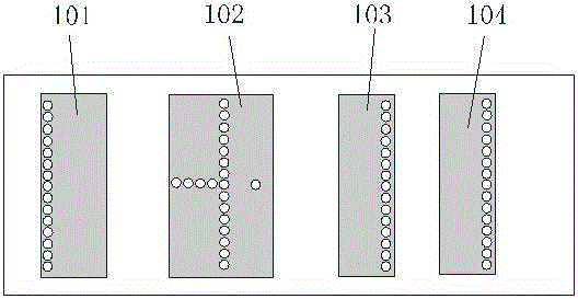
[0025] Such as figure 1 , 2 As shown, a Yagi antenna of a magnetic dipole includes four similar metal patch radiating units, specifically including an excitation unit and three coupling units; respectively, a reflection coupling unit 101, an excitation unit 102, and a first directing coupling unit Unit 103 , the second leads to the coupling unit 104 .

[0026] Four metal patch radiating units are printed on a dielectric plate 201 with a thickness of 3mm, and each metal patch radiating unit is arranged on the dielectric plate in parallel with intervals between adjacent metal patch radiating units, and the order of them is reflection coupling unit 101, The excitation unit 102 , the first leads to the coupling unit 103 , and the second leads to the coupling unit 104 .

[0027] The excitation unit 102 includes upper and lower rectangular metal patches 202 and 203 , and first and second shorting pin groups 204 and 205 . Wherein, the upper and lower metal patches 202 and 203 are ...


PUM


Abstract

The invention discloses a magnetic dipole yagi antenna. The magnetic dipole yagi antenna comprises four side-by-side and parallel metal patch radiating units which are printed on a dielectric plate, wherein the metal patch radiating units are a reflection coupling unit, an excitation unit, a first lead coupling unit and a second lead coupling unit in order. Adjacent metal patch radiating units are spaced. The excitation unit comprises upper and lower rectangular metal patches and a short circuit pin group. Upper and lower rectangular metal patches are respectively located on upper and lower surfaces of the dielectric plate. Upper and lower rectangular metal patches are communicated through the short circuit pin group. The reflection coupling unit, the first lead coupling unit and the second lead coupling unit respectively comprise first and second rectangular metal patches and a third short circuit pin group. First and second rectangular metal patches are respectively located on upper and lower surfaces of the dielectric plate. First and second rectangular metal patches are communicated through the third short circuit pin group. According to the invention, the magnetic dipole radiating units are used to construct a yagi antenna array, and the magnetic dipole yagi antenna has the characteristics of low profile, wide frequency band and good directivity.

Description

technical field [0001] The present invention relates to the field of antenna design, more specifically, to a magnetic dipole Yagi antenna. Background technique [0002] The existing electric dipole Yagi antenna array realizes the polarization characteristic parallel to the plane where the antenna is located. If vertical polarization is to be provided, the antenna needs to be perpendicular to the floor, which occupies a large antenna height, which seriously affects the aesthetics and concealment of the antenna. . Contents of the invention [0003] In order to overcome at least one defect (deficiency) of the above-mentioned prior art, the present invention provides a magnetic dipole Yagi antenna. This antenna uses a magnetic dipole radiation unit to construct a Yagi antenna, which has the characteristics of low profile, wide frequency band and good directivity. [0004] In order to solve the problems of the technologies described above, the technical solution of the presen...

Claims


Application Information

Patent Timeline
IPC IPC(8): H01Q1/38H01Q1/50H01Q19/10H01Q19/30
Inventor 梁琪梁志禧龙云亮李元新
Owner SYSU CMU SHUNDE INT JOINT RES INST
Why Eureka
Try Eureka