Photon-counting detector calibration

A photon counting and detector technology, applied in instruments, measuring devices, scientific instruments, etc., can solve the problems of complex and inaccurate analytical methods

Active Publication Date: 2015-12-23
KONINKLJIJKE PHILIPS NV
View PDF3 Cites 19 Cited by
  • Summary
  • Abstract
  • Description
  • Claims
  • Application Information

AI Technical Summary

Problems solved by technology

Analytical methods are therefore complex and inaccurate

Method used


Image

  • Photon-counting detector calibration
  • Photon-counting detector calibration
  • Photon-counting detector calibration

Examples


Embodiment Construction

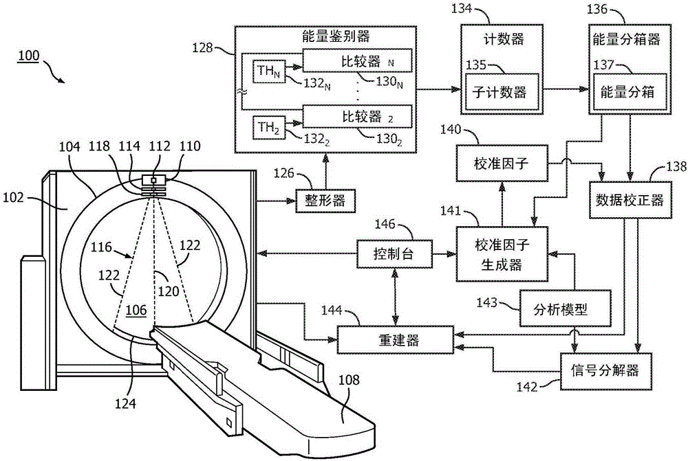
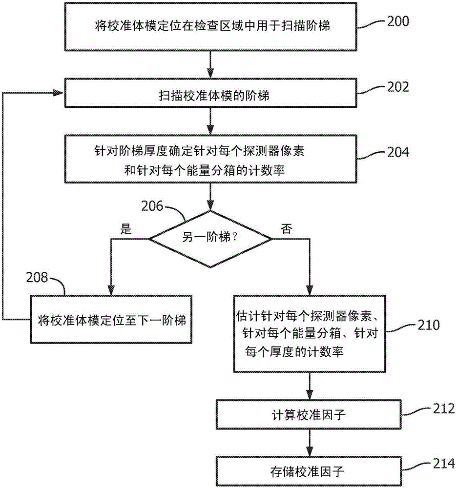
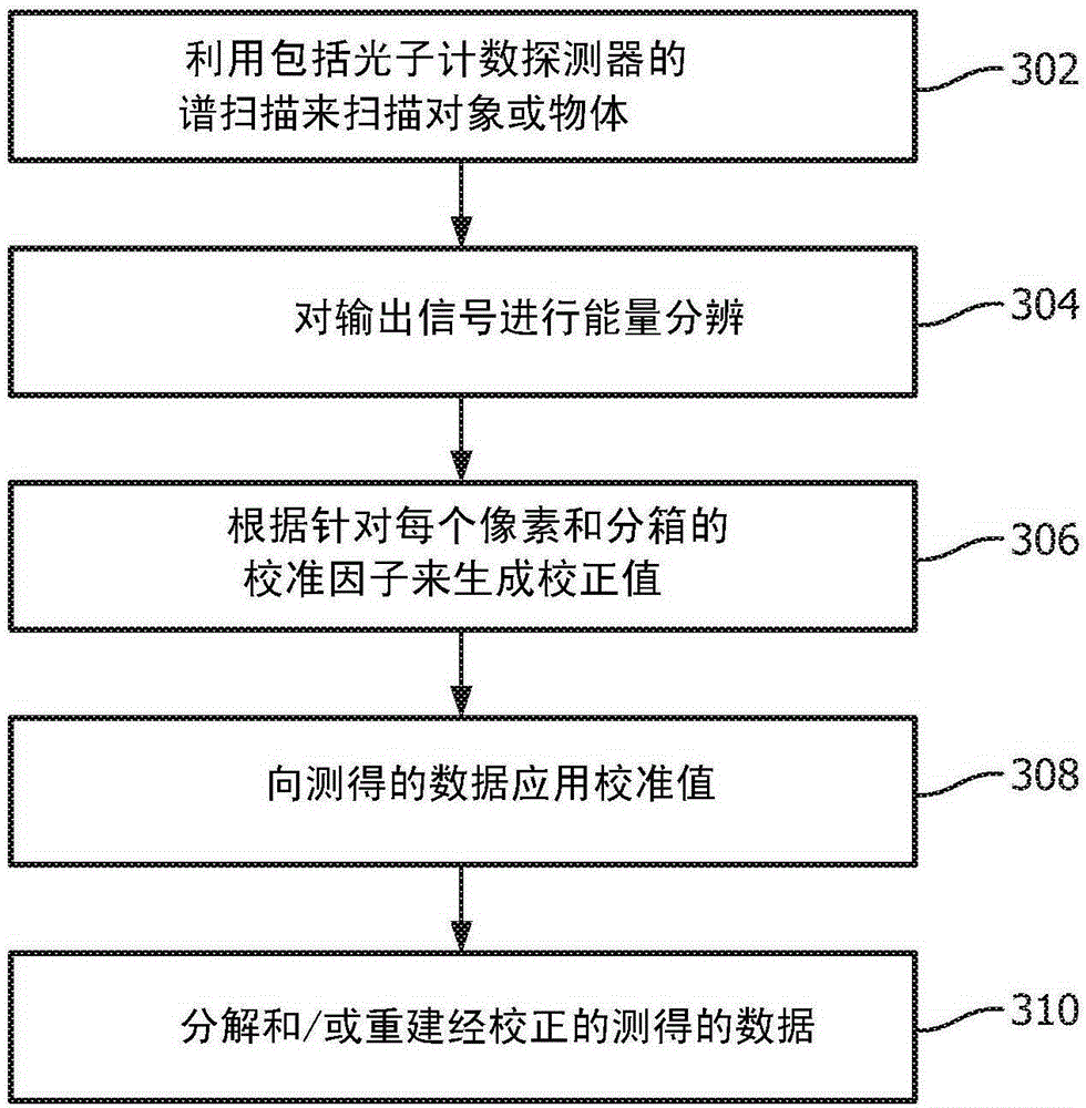
[0021] A photon counting detector calibration is described below. The calibration involves performing a single scan of a single phantom of a single material and multiple steps of different but uniform thicknesses, and mapping the results to an analytical (mathematical) model to generate calibration (or scaling) factors, the The calibration factor can then be applied to the measurement signal from the subject or objects to calibrate or transform the measurement signal to fit the analysis model, thereby correcting the measurement data and generating corrected measurement data.

[0022] first reference figure 1 , schematically illustrates an imaging system 100 such as a computed tomography (CT) scanner.

[0023] The imaging system 100 includes a fixed gantry 102 and a rotating gantry 104 rotatably supported by the fixed gantry 102 . The rotating gantry 104 rotates about an examination region 106 about a longitudinal or z-axis. A subject support 108 , such as a hospital couch, ...


PUM


Abstract

A method includes determining calibration factors for calibrating photon-counting detectors of a spectral imaging system by combining a heuristic calibration of the photon-counting detectors and an analytical calibration of the photon-counting detectors and generating a set of photon-counting calibration factors based on the combining of the a heuristic calibration and the analytical calibration. The photon-counting calibration factors, when applied to measured energy-resolved data from the photon-counting detectors of a spectral CT scan of a subject or object, mitigate spectral distortion caused by a radiation intensity profile shaper that filters a radiation beam of the spectral CT scan.

Description

technical field [0001] The following relates generally to calibrating imaging detectors, and more specifically to calibrating photon counting imaging detectors, and is described with particular application to spectral computed tomography (CT). Background technique [0002] A non-spectral CT scanner includes an x-ray tube mounted on a rotatable gantry opposite a detector array positioned across the examination region. The gantry, and thus the x-ray tube, is rotatable around the examination area. The X-ray tube is configured to emit X-ray radiation. Radiation intensity profile shapers such as the known "bow-tie" filters attenuate emitted x-ray radiation directed towards the examination region to a greater extent in the peripheral region relative to the more central region, thereby reducing the magnetic flux in the outer region, which improves radiation efficiency. [0003] A source collimator collimates the filtered x-ray radiation to produce a radiation beam in the directi...

Claims


Application Information

Patent Timeline
Patent Type & Authority Applications(China)
IPC IPC(8): A61B6/03A61B6/00G01T1/00
CPCA61B6/4241A61B6/032A61B6/4233A61B6/482A61B6/583A61B6/585G01T1/161G01T1/169G01T1/171G01T7/005
Inventor C·O·斯基拉A·特伦H·德尔E·勒斯尔
Owner KONINKLJIJKE PHILIPS NV
Why Eureka
Try Eureka