
Tamping unit for a track tamping machine

A technology of tamping machines and equipment, applied in the direction of tracks, roads, ballast layers, etc., can solve the problems of reducing the degree of ballast entering, reducing the elasticity of hydraulic hoses, and reducing the compaction effect, and achieves simple structure and simple Structural conditions, the effect of not being prone to failure

Inactive Publication Date: 2015-12-23
HP3 REAL GMBH
View PDF8 Cites 29 Cited by
  • Summary
  • Abstract
  • Description
  • Claims
  • Application Information

AI Technical Summary

Problems solved by technology

It is also known that when controlling the feed cylinder, the amplitude is reduced due to the elasticity of the hydraulic hose and thus the compaction effect
It is known from various studies that a reduced tamping amplitude adversely affects the compaction effect and likewise reduces the ingress of ballast

Method used

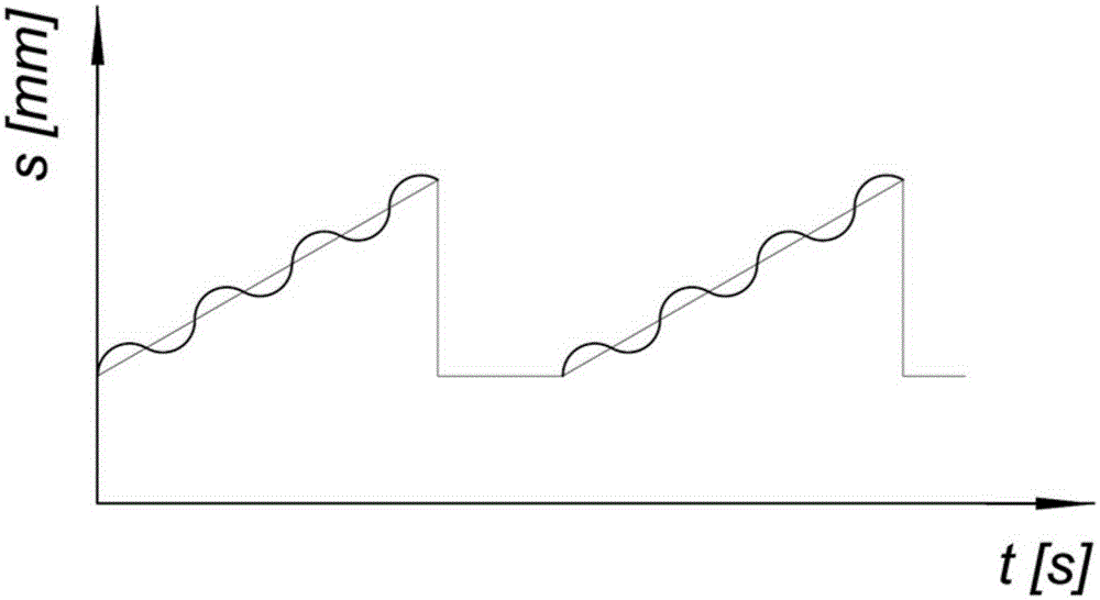

Image

  • Tamping unit for a track tamping machine
  • Tamping unit for a track tamping machine

Examples


Embodiment Construction

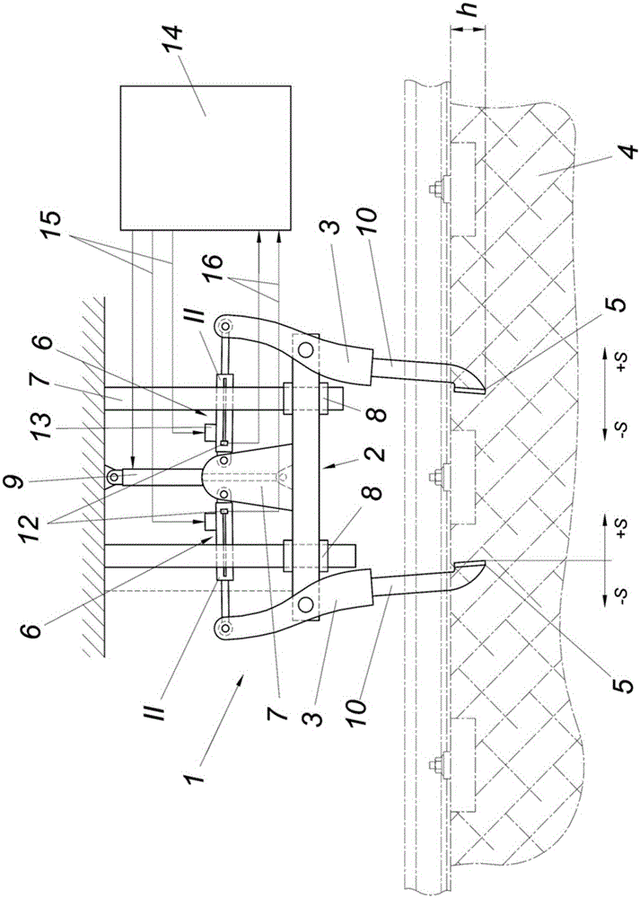
[0019] The tamping device 1 for a track tamping machine also comprises a tamping tool pair with a tamping tool 3 arranged on a support 2 and designed as a pendulum, the pair of tamping tools is defined for insertion into the lower tamping of the ballast bed 4 The pick ends 5 are drivable in opposite directions by means of the vibration drive 6 and can be advanced hydraulically against each other by an advance displacement s. The carriage 2 is guided in a height-adjustable manner in a tamping device frame 7 with a guide 8 and can be moved into a desired height position by means of an adjusting cylinder 9 . The tamping tool 3 is designed as a double arm, which is pivotably mounted on the support 2 . One arm of each tamping tool 3 is formed by a tamping pick 10 , and a hydraulic cylinder 11 acts on the other arm of each tamping tool 3 , the other end of which is in turn supported on the support 2 .

[0020] Each tamping tool 3 of the tamping tool pair is equipped with a hydrauli...


PUM


Abstract

The invention relates to a tamping unit (1) for a track tamping machine, comprising tamping tool pairs, which are arranged on a support (2) that is guided in a tamping unit frame in a height-adjustable manner and which are designed as rocking levers. The lower tamping pick ends (5) of the tamping tool pairs, which lower tamping pick ends are intended to be plunged into a ballast bed (4), can be driven in opposite directions by means of an oscillating drive (6) and can be brought next to each other hydraulically. According to the invention a hydraulic cylinder (11) and a travel sensor (12) for determining the hydraulic cylinder position are associated with each of the tamping tools (3) of a tamping tool pair in order to increase the stability of the tamping unit, wherein the hydraulic cylinders (11) form the drive for bringing the lower tamping pick ends next to each other and the oscillating drive (6) of the tamping tools (3) and the hydraulic cylinders (11) are controlled in dependence on the travel sensor signals.

Description

technical field [0001] The invention relates to a tamping device for a rail tamping machine, which has a pair of tamping tools designed as swing rods, arranged on a height-adjustably guided support in a frame of the tamping device, the tamping tools Pairs of lower tamping pick ends defined for insertion into the ballast bed can be driven against each other by vibratory drives and can be hydraulically fed into each other. Background technique [0002] The tamping device uses a tamping tool to penetrate the ballast of the ballast bed in the area between two sleepers (intermediate cell) into the ballast in the area where the sleeper is supported under the track, and with a tamping pick, it can Dynamic vibration between opposing tamping picks that feed each other compacts ballast. The tamping device can tamp one, two or several sleepers in one working cycle (DE2424829A). [0003] The movement of the tamping equipment consists of the vertical insertion of the tamping pick into ...

Claims


Application Information

Patent Timeline
Patent Type & Authority Applications(China)
IPC IPC(8): E01B27/16
CPCE01B27/16
Inventor B.利希特伯格
Owner HP3 REAL GMBH
Learn More