
Flow rate control valve for flow rate control device

A technology of flow control device and flow control valve, which is applied in the direction of valve device, valve operation/release device, diaphragm valve, etc.

Inactive Publication Date: 2015-12-23
FUJIKIN INC
View PDF8 Cites 9 Cited by
  • Summary
  • Abstract
  • Description
  • Claims
  • Application Information

AI Technical Summary

Problems solved by technology

[0011] However, when the number of necessary gas supply lines increases, the depth L of the integrated gas supply device inevitably increases, leading to an increase in the size of the integrated gas supply device.

Method used


Image

  • Flow rate control valve for flow rate control device
  • Flow rate control valve for flow rate control device
  • Flow rate control valve for flow rate control device

Examples


no. 1 approach

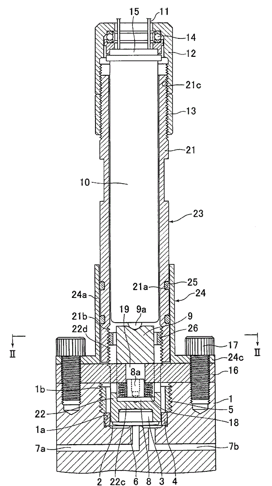
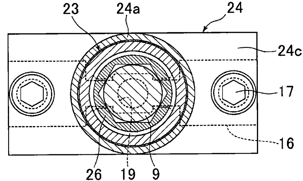
[0100] figure 1 and even Figure 8 It is a figure showing the first embodiment of the present invention, figure 1 It is a longitudinal sectional view of the normally closed piezoelectric element-driven metal diaphragm control valve according to the first embodiment of the present invention, figure 2 for figure 1 The II-II section outline diagram.

[0101] The control valve is composed of the following components: a valve main body 1 provided with a valve chamber hole 1a; a metal diaphragm valve body 2 arranged opposite to a valve seat 6 formed on the bottom surface of the valve chamber hole 1a; Insert the lower support cylinder 22 of the piezoelectric element 10 above the metal diaphragm valve body 2 of the hole 1a; insert the lower support cylinder 22 in the horizontal direction and fix it on the support stand 16 of the valve main body 1; insert it into the support The disc spring bearing platform 8 and the disc spring 18 between the platform 16 and the bottom wall 21...


PUM


Abstract

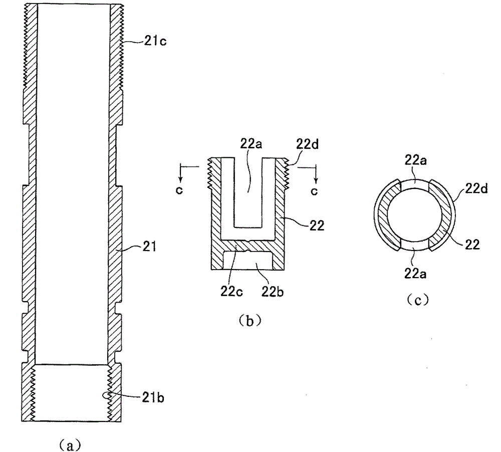
By being designed to simplify and reduce the size of the structure of a piezoelectric element-driven metal diaphragm control valve to be used in flow rate control devices, etc. and to simplify assembly and maintenance thereof, the present invention makes it possible to respond to the demand for more types of supply gases and supply circuits without causing increases in the size of integrated gas supply units for semiconductor-manufacturing devices, etc. The present invention is obtained from: a main valve body (1), which is equipped with a valve chamber hole (1a) that is open at the upper end and has a valve seat (6), and a fluid inlet path (7a) and a fluid outlet path (7b) communicating with same; an inverted dish-shaped metal diaphragm valve body (2), which is disposed above the valve seat (6) facing same and the outer circumferential edge of which is fixed to the bottom surface of the valve chamber hole (1a); a pressing screw (5), which is screwed into the valve chamber hole (1a) to press and fix the outer circumferential edge of the metal diaphragm valve body (2); a lower support cylinder (22), which passes through the inside of the pressing screw (5) and is inserted into the valve chamber hole (1a), is provided with a diaphragm press (3) below the bottom wall of the tip, and is provided with rectangular notches (22a) extending from the upper end to the middle of the side walls so as to pass through the side walls; a cylindrical upper support cylinder (21), which is screwed onto the upper end of the lower support cylinder (22) to form a support cylinder (23); a disc spring cradle (8) loaded on the bottom wall of the lower support cylinder (22) and having a holder section (8a); a disc spring (18) loaded on the disc spring cradle (8); a support frame (16), which is inserted in the notches (22a) of the lower support cylinder (22) and disposed horizontally, which has, at the center, a disc spring cradle guiding hole (19) for holding the tip of the disc spring holder section (8a), and which is provided with bolt insertion holes (20) at both ends; a lower cradle (9) loaded above the disc spring cradle guiding hole (19) of the support frame (16); a piezoelectric element (10) inserted inside the support cylinder (23) above the lower cradle (9); a guide (24), which is provided with a guide tube (24a) and flanges (24c) protruding from the lower end thereof to both sides, which is for inserting the support cylinder (23) inside the guide tube (24a) so as to allow vertical movement, and the flanges (24c) of which are made to face the two ends of the support frame (16) and are fixed to the main valve body (1) together with the support frame (16) using fixing bolts (17); and a positioning nut (12) screwed onto the upper end of the upper support cylinder (21). The support cylinder (23) is pushed upward by the expansion of the piezoelectric element (10) and the metal diaphragm valve body (2) is separated from the valve seat (6) by the elastic force of the metal diaphragm valve body.

Description

technical field [0001] The present invention relates to an improvement of a flow control valve for a flow control device. Simplification and miniaturization, and ease of assembly, maintenance and inspection can achieve further miniaturization of a flow control device including the flow control valve, an integrated gas supply device for semiconductor manufacturing equipment using the flow control device, and the like. Background technique [0002] Integrated gas supply devices used in semiconductor manufacturing equipment, etc. are generally Figure 12 As shown, it is constituted by connecting two-way on-off valves 51A, 51B, three-way on-off valves 52A, 52B, flow control device 53, etc. in series using blocks 54 to 58 provided with gas flow paths, so that One gas supply line (pipeline) is formed, and the plurality of gas supply lines are arranged and fixed to the blocks 55 and 59 in parallel (Japanese Patent Application Laid-Open No. 5-172265, etc.). [0003] In addition, as...

Claims


Application Information

Patent Timeline
Patent Type & Authority Applications(China)
IPC IPC(8): F16K31/02F16K27/02
CPCF16K7/14F16K27/0236F16K31/007F16K25/005F16K31/004
Inventor 广濑隆山路道雄吉田俊英执行耕平
Owner FUJIKIN INC
Learn More