Anti-blocking fertilizer distributor

A fertilizer applicator and anti-clogging technology, which is applied to fertilization devices, fertilizer distributors, applications, etc., can solve problems such as increased labor load, uneven feeding, and regardless of soil, and achieve the effect of improving operating efficiency and quality

Inactive Publication Date: 2015-12-30
CHONGQING XINSHUI MACHINERY MFG
View PDF0 Cites 5 Cited by
  • Summary
  • Abstract
  • Description
  • Claims
  • Application Information

AI Technical Summary

Problems solved by technology

Fertilization must consider the factors of the soil itself, and it is not possible to apply fertilizer blindly. This is because: first, only when the soil has insufficient supply of a certain nutrient, it is necessary to apply fertilizer, and it is not necessary to apply all the necessary elements to the soil. Otherwise, the soil ( or atmosphere) of nutrients can cause waste and even cause crop poisoning
Second, after the fertilizer is applied to the soil, there will be a series of changes, which will affect the fertilizer effect to varying degrees. If the soil is not considered, it is impossible to talk about the real rational fertilization
[0003] At present, in the fertilization of base fertilizer, anti-clogging fertilizer applicators are usually used for operation, and the mixed ammonia fertilizer and phosphate fertilizer are put into the soil, but the traditional anti-clogging fertilizing machines are not equipped with a stirring mechanism, and the fertilizer outlet is small. In the process of fertilization, the fertilizer outlet is often blocked and the feeding is uneven, especially when the fertilizer is wet or in rainy weather, the fertilizer is more likely to block the fertilizer outlet and affect the normal operation, and manual cleaning will increase the workload. , affecting the fertilization efficiency

Method used


Image

  • Anti-blocking fertilizer distributor

Examples


Embodiment Construction

[0013] The present invention will be described in further detail below by means of specific embodiments:

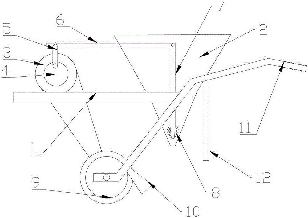
[0014] Frame 1, hopper 2, driving wheel 3, cam 4, ejector rod 5, cross bar 6, stirring rod 7, inverted tooth 8, wheel 9, baffle plate 10, handle 11, bicycle foot 12.

[0015] The embodiment is basically as attached figure 1 Shown: including frame 1, two wheels 9 are installed on the bottom of frame 1, gasoline engine is installed on the left side of frame 1, coaxial drive wheel 3 and cam 4 are connected on the gasoline engine, drive wheel 3 and wheel 9 Connected by a belt; the right side of the frame 1 is a funnel-shaped hopper 2, the outlet of the hopper 2 is located at the bottom of the hopper 2, and the right side of the hopper 2 is two handles 11, and the grip of the handle 11 is provided with anti-slip protrusions ; The frame 1 is also equipped with two telescopic car feet 12, which can play a role of balance support when the fertilizer applicator stops. A vertical...


PUM


Abstract

The invention relates to the technical field of agricultural machinery equipment, in particular to an anti-blocking fertilizer distributor. The anti-blocking fertilizer distributor comprises a rack, wherein a driving wheel, a wheel, a hopper and a handle are arranged on the rack, the driving wheel is connected with the wheel, a discharge port of the hopper is located at the bottom of the hopper, a vertical stirring rod is arranged in the hopper, and the bottom end of the stirring rod is arranged corresponding to the discharge port; a cam which is coaxial with the driving wheel is arranged beside the driving wheel, a horizontal rod is glidingly connected and mounted to the hopper, one end of the horizontal rod and a top rod of the cam are arranged in a matched manner, and the other end of the horizontal rod is connected with the top end of the stirring rod. According to the equipment, the cam and the stirring rod are arranged, under the gravity action of the cam and the stirring rod, the stirring rod moves up and down and stirs the fertilizer in the hopper, the bottom end of the of the stirring rod can stir the fertilizer in the discharge port, the fertilizer can be prevented from being blocked and blocking the discharge port to cause the phenomenon that no fertilizer is discharged from the hopper or the discharge fertilizer is not uniform, work of manually cleaning the blocked hopper is reduced, and the operation efficiency is improved.

Description

technical field [0001] The invention relates to the technical field of agricultural machinery, in particular to an anti-clogging fertilizer. Background technique [0002] When the soil cannot provide the nutrients needed for crop growth and development, the act of supplementing the crops with artificial nutrients is called fertilization. Fertilization must consider the factors of the soil itself, and it is not possible to apply fertilizer blindly. This is because: first, only when the soil has insufficient supply of a certain nutrient, it is necessary to apply fertilizer, and it is not necessary to apply all the necessary elements to the soil. Otherwise, the soil ( or atmosphere) of nutrients can cause waste and even cause crop poisoning. Second, after the fertilizer is applied to the soil, there will be a series of changes, which will affect the fertilizer effect to varying degrees. If the soil is not considered, it is impossible to talk about real and reasonable fertiliza...

Claims


Application Information

Patent Timeline
Patent Type & Authority Applications(China)
IPC IPC(8): A01C15/12
Inventor 廖佳袁
Owner CHONGQING XINSHUI MACHINERY MFG
Why Eureka
Try Eureka