Novel cutting system for reinforcing steel bars

A new type of steel bar technology, which is applied in the field of new steel bar cutting system, can solve the problems of not fast enough cutting, low work efficiency, tool breakage, etc., and achieve the effect of simple structure, high work efficiency and improved efficiency

Inactive Publication Date: 2015-12-30
CHINA JILIANG UNIV
View PDF9 Cites 9 Cited by
  • Summary
  • Abstract
  • Description
  • Claims
  • Application Information

AI Technical Summary

Problems solved by technology

However, the existing steel bar cutting machine has low working efficiency, and the cutting is not fast enough

Method used


Image

  • Novel cutting system for reinforcing steel bars

Examples


Example Embodiment

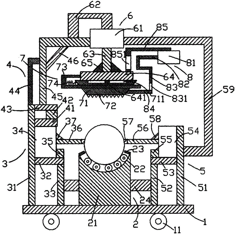
[0019] Such as figure 1 As shown, the steel bar cutting system of the present invention includes a bottom plate 1, a support platform device located above the bottom plate 1, a first cylinder device 3 located on the left side of the support platform device 2, and a first cylinder device 3 located above the first cylinder device 3. The supporting device 4, the second cylinder device 5 located on the right side of the supporting table device 2, the third cylinder device 6 provided on the supporting device 4, the intercepting device 7 located below the third cylinder device 6, and the The fourth cylinder device 8 on the right side of the third cylinder device 6.

[0020] Such as figure 1 As shown, the bottom plate 1 is a rectangular parallelepiped, the bottom plate 1 is placed horizontally, the bottom plate 1 is provided with first rollers 11, and the first rollers 11 are provided with two and are located on the left and right sides respectively. The roller 11 is cylindrical, and ...


PUM


Abstract

A novel cutting system for reinforcing steel bars comprises a bottom plate, a supporting platform device, a first air cylinder device, a supporting device, a second air cylinder device, a third air cylinder device, a cutting device and a fourth air cylinder device, wherein first rollers are arranged on the bottom plate; the supporting platform device comprises a supporting platform, second rollers, positioning rods and a first transverse rod; the first air cylinder device comprises a first supporting rod, a second transverse rod, a second supporting rod, a first air cylinder, a first fixing block, a first push rod, a first friction block and a first triangular block; the supporting device comprises a third transverse rod, a second fixing block, a fourth transverse rod, a first bracket, a second bracket and a first inclined rod; the second air cylinder device comprises a third supporting rod, a fourth supporting rod, a fifth transverse rod, a second air cylinder, a third fixing block, a second push rod, a second friction block, a second triangular block and a first fixing frame. The system can cut the reinforcing steel bars quickly, is high in working efficiency, quick and high in automation degree and can reduce the labor intensity.

Description

Technical field: [0001] The invention relates to the technical field of construction machinery, in particular to a novel steel bar cutting system. Background technique: [0002] The steel bar cutting machine is a more commonly used equipment for cutting steel bars, so that it can be more convenient to cut steel bars according to needs. However, the existing steel bar cutting machine has low working efficiency, and the cutting is not fast enough to meet the current efficiency requirements, and it is easy to cause the cutter to break and increase the cost. [0003] Therefore, it is necessary to provide a new technical solution to solve the above technical problems. Invention content: [0004] The object of the present invention is to provide a new steel bar cutting system that can effectively solve the above technical problems. [0005] In order to solve the above technical problems, the present invention adopts the following technical solutions: [0006] A new steel bar ...

Claims


Application Information

Patent Timeline
IPC IPC(8): B21F11/00
CPCB21F11/00
Inventor 叶纲
Owner CHINA JILIANG UNIV
Why Eureka
Try Eureka