
Visual positioning method of mobile manipulator

A technology of visual positioning and mobile operation, applied in the directions of manipulators, program-controlled manipulators, chucks, etc., can solve the problems of bonding phenomenon, improper placement of workpieces, positioning errors, etc., to ensure material transportation, stabilize material transportation, and improve robustness. performance effect

Inactive Publication Date: 2015-12-30
INST OF AUTOMATION CHINESE ACAD OF SCI
View PDF5 Cites 1 Cited by
  • Summary
  • Abstract
  • Description
  • Claims
  • Application Information

AI Technical Summary

Problems solved by technology

[0002] In the process of repeatedly picking and placing workpieces, the mobile manipulator will cause positioning errors due to some internal factors or external interference, so that it cannot pick and place workpieces stably and reliably, and may even cause some accidents. Therefore, mobile manipulators are used in industrial material transportation. Positioning is needed to eliminate this error in
In material transportation, for some specific workpieces, it is necessary to add specific materials (such as polyester sheets) to the clamping fingers to improve the friction with the surface of the workpiece and prevent accidents caused by the workpiece falling during transportation; however, due to Due to the action of the clamping force, the workpiece may be bonded to the added material of the finger, so that dragging occurs when the workpiece is placed or even cannot be separated from the clamping finger.
On the other hand, in the industry, the working surface is often inclined. At this time, the height of the workpiece is very important. If the workpiece is too high from the table when the clamping jaw is opened, it is likely to cause the workpiece to be placed incorrectly and fall. , which is often the case when the mobile manipulator works on multiple workbenches at the same time
In order to improve efficiency, the end effector of the mobile manipulator often operates multiple workpieces at the same time. At this time, if the end effector has a rotation angle error, it will bring a large position error to the edge workpiece, resulting in some workpieces not being placed in place.

Method used


Image

  • Visual positioning method of mobile manipulator
  • Visual positioning method of mobile manipulator
  • Visual positioning method of mobile manipulator

Examples


Embodiment Construction

[0034] The technical problems solved by the embodiments of the present invention, the technical solutions adopted and the technical effects achieved are clearly and completely described below in conjunction with the accompanying drawings and specific embodiments. Apparently, the described embodiments are only some of the embodiments of the present application, not all of them. Based on the embodiments in the present application, all other equivalent or obviously modified embodiments obtained by persons of ordinary skill in the art without creative efforts fall within the protection scope of the present invention. Embodiments of the invention can be embodied in many different ways as defined and covered by the claims.

[0035] It should be noted that, in the following description, many specific details are given for the convenience of understanding. It may be evident, however, that the present invention may be practiced without these specific details.

[0036] It should be no...


PUM


Abstract

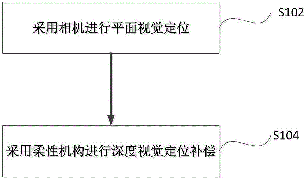
The invention discloses a visual positioning method of a mobile manipulator. The visual positioning method at least comprises the following steps: performing planar visual positioning by a camera, wherein the planar visual positioning comprises positioning of two translation degrees of freedom and one rotation degree of freedom; performing deep visual positioning compensation by a flexible mechanism, wherein the deep visual positioning comprises positioning of translation degree of freedom, preferably, the planar visual positioning comprises a step of obtaining an error of the translation degrees of freedom and an error of the rotation degree of freedom through a template matching mode. According to the visual positioning method, the technical problem of how to improve the robustness of the mobile manipulator is at least solved.

Description

technical field [0001] The embodiments of the present invention relate to the field of industrial technology, in particular to a visual positioning method for a mobile operating machine. Background technique [0002] In the process of repeatedly picking and placing workpieces, the mobile manipulator will cause positioning errors due to some internal factors or external interference, so that it cannot pick and place workpieces stably and reliably, and may even cause some accidents. Therefore, mobile manipulators are used in industrial material transportation. Need to use positioning to eliminate this error. In material transportation, for some specific workpieces, it is necessary to add specific materials (such as polyester sheets) to the clamping fingers to improve the friction with the surface of the workpiece and prevent accidents caused by the workpiece falling during transportation; however, due to Due to the effect of the clamping force, the workpiece may be bonded to ...

Claims


Application Information

Patent Timeline
IPC IPC(8): B25J9/12B25J15/12B25J13/08B25J19/00
Inventor 王伟肖伟李晓琪邢春龙
Owner INST OF AUTOMATION CHINESE ACAD OF SCI
Learn More