Braking control method for train

A braking control and train technology, applied in the direction of brakes, braking action starting devices, vehicle components, etc., can solve the problems of not guaranteeing that the EB trigger curve will not be triggered, and failing to follow the design principles well.

Active Publication Date: 2015-12-30
浙江众合科技股份有限公司
View PDF5 Cites 17 Cited by
  • Summary
  • Abstract
  • Description
  • Claims
  • Application Information

AI Technical Summary

Problems solved by technology

However, although the FSB trigger curve determined by the above method can ensure that the EB trigger curve is triggered infrequently, it cannot fully and effectively control the train braking, and cannot guarantee that EB will not be triggered during the process from triggering the FSB trigger curve to the completion of the FSB. Trigger curves, i.e. ATP on-board systems still trigger unnecessary emergency braking in certain situations, so the above method does not follow the design principles very well

Method used


Image

  • Braking control method for train
  • Braking control method for train
  • Braking control method for train

Examples


Embodiment Construction

[0043] In order to make the above-mentioned objects, features and advantages of the present invention more obvious and understandable, the specific embodiments of the present invention will be described in detail below with reference to the accompanying drawings.

[0044] In the following description, many specific details are explained in order to fully understand the present invention. However, the present invention can be implemented in many other ways different from those described here, and those skilled in the art can make similar popularizations without violating the connotation of the present invention. Therefore, the present invention is not limited by the specific implementation disclosed below.

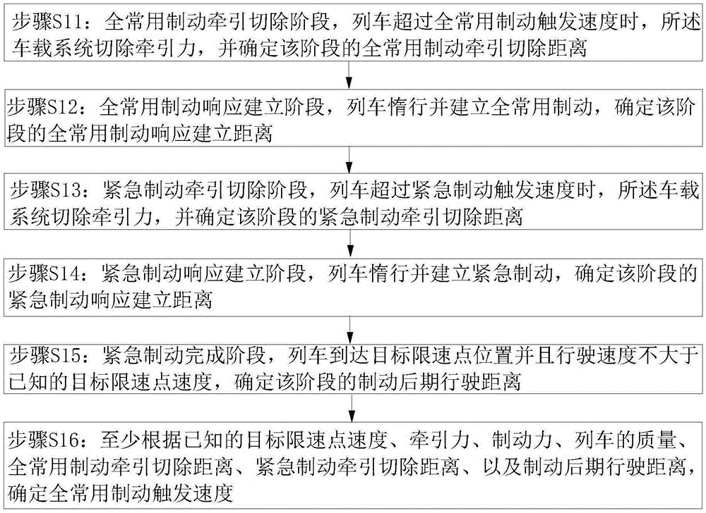
[0045] figure 1 Shows the flow chart of determining the full service brake trigger speed of the automatic train protection vehicle-mounted system of the embodiment of the present invention. First, set a full service brake trigger speed v X , Determine the full service brake trig...


PUM


Abstract

The invention discloses a braking control method for a train. The driving distance of the train is determined by five stages of a full service braking traction removing stage, a full service braking response establishing stage, an emergency braking traction removing stage, an emergency braking response establishing stage and an emergency braking finishing stage in a sub-stage way, and further the full service braking trigger speed is determined by backward recurrence, the distance between the position where the train is positioned and a speed limit point of a target and the driving speed of a current train are guaranteed, and the condition that emergency braking is trigged when full service braking is triggered is avoided.

Description

[0001] The patent application for the present invention is a divisional application of the invention titled "A braking control method for an automatic train protection vehicle-mounted system". The original application was filed on January 24, 2014, and the application number was 2014100338164. Technical field [0002] The invention relates to the field of train automatic protection vehicle-mounted systems, in particular to a brake control method of train automatic protection vehicle-mounted systems. Background technique [0003] According to the existing ATP (Automatic Train Protection, automatic train protection) on-board technology, an EB (Emergency Brake) trigger curve is derived from the distance between the train and the target speed limit position and the speed of the train. When the speed of the train at a certain position exceeds the point on the EB trigger curve, the on-board system will trigger the emergency brake. Once the emergency brake is triggered, the train will be ...

Claims


Application Information

Patent Timeline
Patent Type & Authority Applications(China)
IPC IPC(8): B60T7/12
CPCB60T7/126
Inventor 滕国栋
Owner 浙江众合科技股份有限公司
Why Eureka
Try Eureka