A Casing Automatic Molding System

A sleeve and mold-loading technology, which is applied to vibrating conveyors, transportation and packaging, conveyor objects, etc., can solve the problem that ceramic sleeves cannot be automatically installed, so as to save manual operation procedures, improve efficiency, and reduce burdens Effect

Active Publication Date: 2017-07-28
浙江西比通信科技有限公司
View PDF5 Cites 0 Cited by
  • Summary
  • Abstract
  • Description
  • Claims
  • Application Information

AI Technical Summary

Problems solved by technology

[0003] The purpose of the present invention is to provide a casing automatic mold loading system to overcome the problem in the prior art that ceramic casings cannot be automatically loaded into fixtures or molds, which is characterized in that it includes vibration feeding sequentially connected along the casing conveying direction device, casing pushing device, casing guiding and positioning device, fixture installation device

Method used


Image

  • A Casing Automatic Molding System
  • A Casing Automatic Molding System
  • A Casing Automatic Molding System

Examples


Embodiment Construction

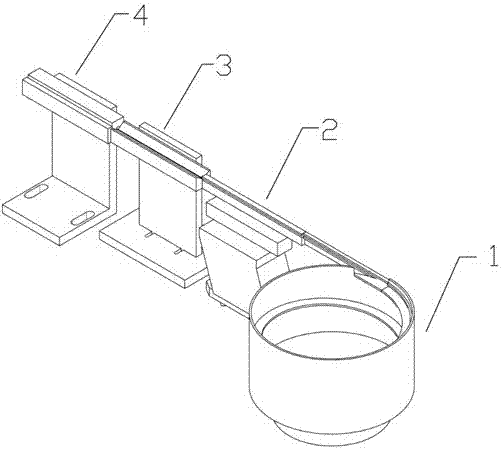
[0019] Embodiments of the present invention will be described in detail below with reference to the accompanying drawings. An automatic die-loading system for bushings, comprising a vibrating feeding device 1, a bushing pushing device 2, a bushing guiding and positioning device 3, and a fixture installation device 4, which are sequentially connected along the bushing conveying direction.

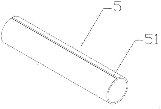
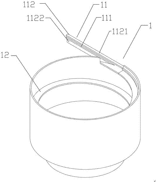
[0020] The vibrating feeding device 1 includes a material output track 11, a vibrator and a spiral material channel 12. The vibrator generates regular vibrations to lift the messy ceramic tubes to be inspected through the spiral material channel to form an orderly casing queue. , and send the casing queue into the casing pushing device 2. The material output track 11 comprises a material output platform 111 and a material output plate 112, and the material output plate 112 comprises a first limiting plate 1121 arranged in parallel on the top of the material output platform, and a first regul...


PUM


Abstract

The invention relates to the technical field of ceramic casing processing, in particular to an automatic molding system for casing. It includes a vibrating feeding device, a casing pushing device, a casing guiding and positioning device, and a clamp installation device connected in sequence along the casing conveying direction. The vibrating feeding device is configured to output the material output track of the material queue, the casing pushing device is configured to push the material pushing track of the casing along the casing transmission direction, and the casing guiding and positioning device is configured to The guide and positioning groove for radial positioning of the sleeve, and the clamp installation device install the clamp for accommodating the sleeve. Automatically organize the scattered ceramic sleeves into queues, unify their opening directions, and install them into the fixture. The tedious manual operation process is saved, the burden on workers is reduced, and the efficiency is improved.

Description

technical field [0001] The invention relates to the technical field of ceramic casing processing, in particular to an automatic molding system for casing. Background technique [0002] During the manufacturing process of the ceramic sleeve of the optical fiber connector, it is necessary to put the semi-finished ceramic sleeve with an opening on the tube wall into a fixture or a mold and fix it for further processing. The fixture or the mold is provided with a positioning part corresponding to the opening on the ceramic sleeve. In most cases, manual operation is required to put the ceramic sleeve into the fixture or mold, and make the opening of the ceramic sleeve cooperate with the positioning component for positioning. The length of the ceramic sleeve is about 11 mm, and the outer diameter is about 3.2 mm. It is small in size, difficult to operate manually, and low in efficiency. Contents of the invention [0003] The purpose of the present invention is to provide a cas...

Claims


Application Information

Patent Timeline
Patent Type & Authority Patents(China)
IPC IPC(8): B65G27/00B65G47/26B65G47/82B65G47/24G02B6/38
Inventor 王丽
Owner 浙江西比通信科技有限公司
Why Eureka
Try Eureka