Presser foot lift shaft oil storage and lubrication structure

A presser foot lifting shaft, lubricating structure technology, applied in lubrication/cooling devices, textiles and papermaking, sewing equipment and other directions, can solve the problems of complicated mold opening and failure to solve effectively, and solve the problems of rusted machine head, noise, etc. Reduced, wear-reducing effect

Active Publication Date: 2018-09-25
BULLMER ELECTROMECHANICAL TECH
View PDF5 Cites 0 Cited by
  • Summary
  • Abstract
  • Description
  • Claims
  • Application Information

AI Technical Summary

Problems solved by technology

However, these measures have not effectively solved the existing problems
A synchronous thick material machine launched by Meiji Company adopts the integrated presser foot lifting shaft model, connects the two fixed shaft sleeves of the casing, and then expands the middle part of the shaft hole for oil storage Lubrication, this solution partially solves the existing problems, but it still cannot fundamentally solve the problem, and at the same time, the mold opening is more complicated when casting the casing

Method used


Image

  • Presser foot lift shaft oil storage and lubrication structure
  • Presser foot lift shaft oil storage and lubrication structure
  • Presser foot lift shaft oil storage and lubrication structure

Examples


Embodiment Construction

[0043] The implementation of the present invention will be illustrated by specific specific examples below, and those skilled in the art can easily understand other advantages and effects of the present invention from the contents disclosed in this specification.

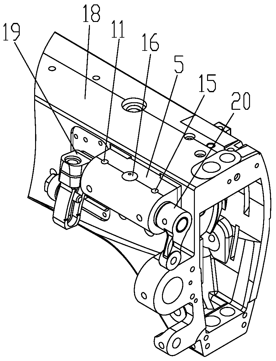
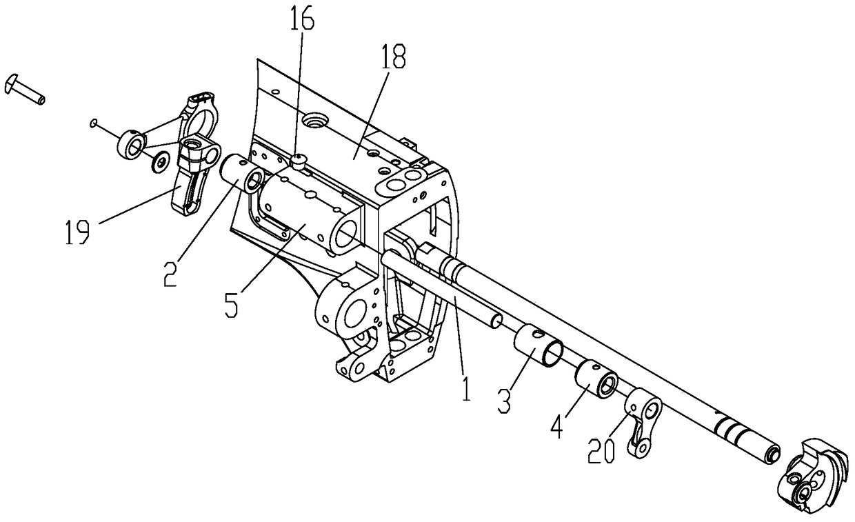
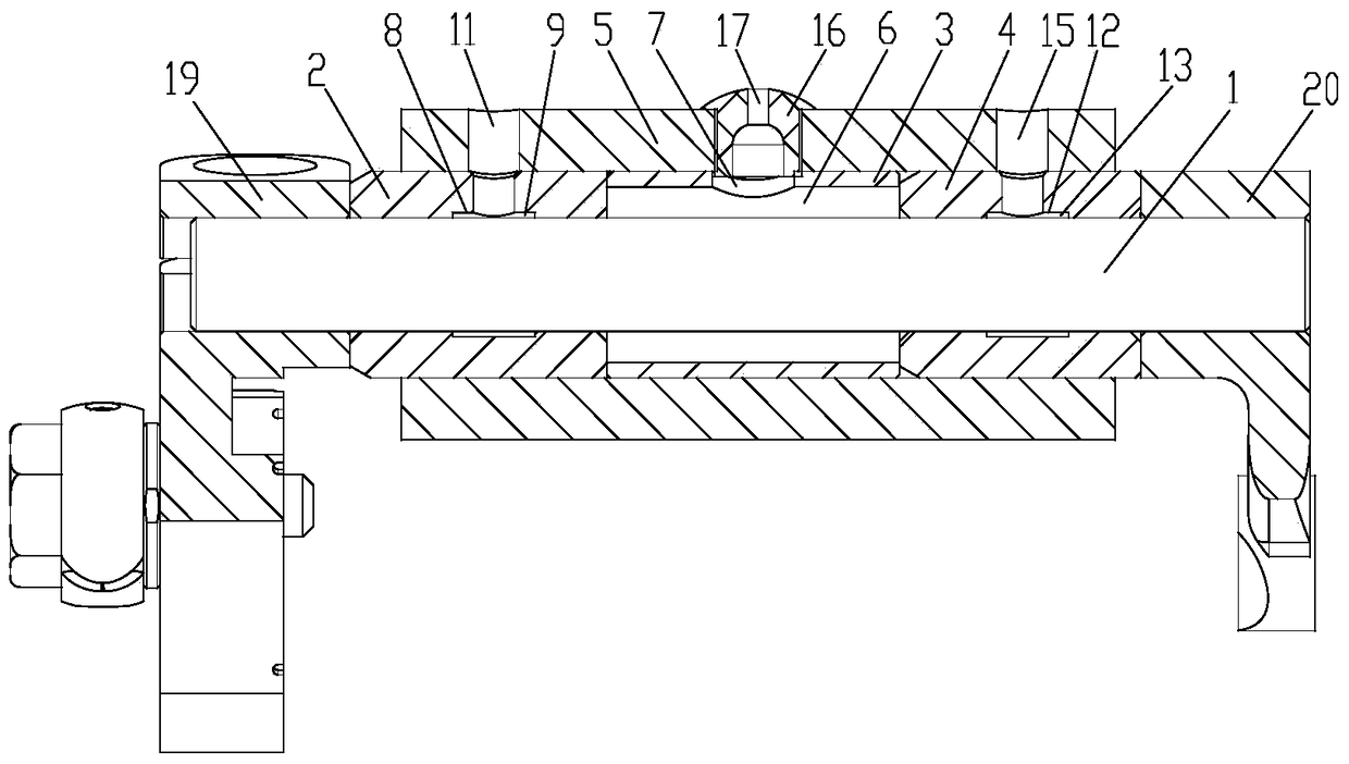
[0044] see Figure 1 to Figure 5 . It should be noted that the structures, proportions, sizes, etc. shown in the drawings attached to this specification are only used to match the content disclosed in the specification, for those who are familiar with this technology to understand and read, and are not used to limit the implementation of the present invention. Limiting conditions, so there is no technical substantive meaning, any modification of structure, change of proportional relationship or adjustment of size, without affecting the effect and purpose of the present invention, should still fall within the scope of the present invention. within the scope covered by the disclosed technical content. At the same ti...


PUM


Abstract

The invention provides a presser foot lift shaft oil storage lubrication structure. The presser foot lift shaft oil storage lubrication structure comprises a lift shaft, wherein a front shaft sleeve, an intermediate pass sleeve and a rear shaft sleeve sequentially sleeve the lift shaft in the axial direction; the outer peripheral surfaces of the front shaft sleeve, the intermediate pass sleeve and the rear shaft sleeve are in interference fit with the inner peripheral surface of a mixed housing; the inner peripheral surfaces of the front shaft sleeve and the rear shaft sleeve are matched with the outer peripheral surface of the lift shaft; an oil storage space is formed between the inner peripheral surface of the intermediate pass sleeve and the outer peripheral surface of the lift shaft and communicated with an outer space through an oil passing hole which penetrates the intermediate pass sleeve and the fixed housing. According to the presser foot lift shaft oil storage lubrication structure, the oil storage space is filled with solid grease, so that the grease can lubricate the lift shaft for a long time, accordingly, the oil adding frequency is reduced, abrasion between the lift shaft and the shaft sleeves is relieved, and noise is lowered; meanwhile, grease cannot permeate to the outside, so that the problem that the grease carries out scrap iron to corrode a machine head is solved.

Description

technical field [0001] The invention relates to an oil storage lubrication structure for a presser foot lifting shaft. Background technique [0002] The lifting shaft of the presser foot, the parts wear and noise caused by lack of lubrication, the wear and tear caused by oil lubrication, and the iron filings rusting the machine head, etc., have always been problems to be solved for synchronous machines. [0003] In response to this problem, different companies have introduced different solutions. Among them, our company adopts the form of steel bushing oil hole to reduce wear, while most companies use the form of copper bushing oil hole to solve this problem. But none of these measures can effectively solve the existing problems. A synchronous thick material machine launched by Meiji Company adopts the integrated presser foot lifting shaft model, connects the two fixed shaft sleeves of the casing, and then expands the middle part of the shaft hole for oil storage Lubricat...

Claims


Application Information

Patent Timeline
Patent Type & Authority Patents(China)
IPC IPC(8): D05B71/00
Inventor 张超波严文进孙连杰
Owner BULLMER ELECTROMECHANICAL TECH
Why Eureka
Try Eureka