Device and method for testing pile-soil interface soil pressure and pore water pressure

A pore water pressure and pore water pressure gauge technology, which is applied in the field of foundation soil survey, construction, infrastructure engineering, etc., can solve the problem that the pile-soil interface is not deep enough, the survival rate is not high, and the earth pressure and pore water pressure are not accurate. Test and other problems, to achieve the effect of simple and compact structure, high measurement accuracy, excellent dynamic and static characteristics

Inactive Publication Date: 2015-12-30
QINGDAO TECHNOLOGICAL UNIVERSITY
View PDF4 Cites 16 Cited by
  • Summary
  • Abstract
  • Description
  • Claims
  • Application Information

AI Technical Summary

Problems solved by technology

Due to limited test conditions and research level, the current research on the pile-soil interface is not deep enough, especially the lack of accurate measurement of the soil pressure and pore water pressure at the pile-soil interface adjacent to the pile body.
Since the survival rate of the traditional earth pressure gauge and pore water pressure gauge is not high at the pile-soil interface, it is not suitable for the test of the pile-soil interface soil pressure and pore water pressure. Therefore, a pile-soil interface soil and pore water pressure test device is designed. and methods, it is the first time to use silicon piezoresistive sensors to test soil pressure and pore water pressure. This kind of sensor uses micro-processed silicon diaphragm as the core component, high-precision integrated piezoresistive sensitive elements, and uses international advanced miniaturization manufacturing and packaging technology. , with exquisite and ingenious micro-encapsulation, the product is small in size, compact in structure, light in weight, strong and durable, has excellent dynamic and static characteristics, and has a wide range of measurements. This kind of testing device and method has not been reported in the literature so far.

Method used


Image

  • Device and method for testing pile-soil interface soil pressure and pore water pressure
  • Device and method for testing pile-soil interface soil pressure and pore water pressure

Examples


Embodiment

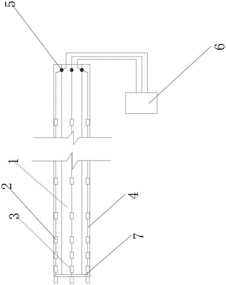
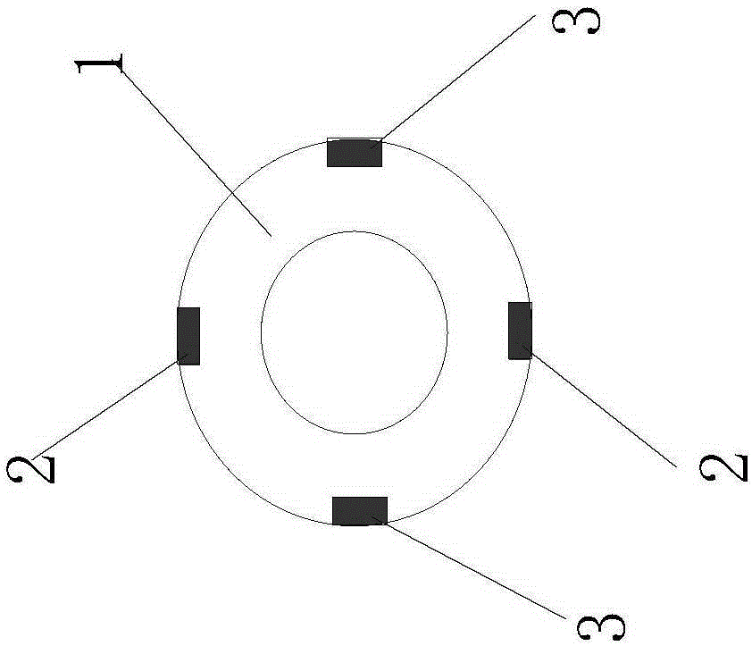
[0016] The main structure of this embodiment includes high-strength prestressed concrete pipe pile 1, silicon piezoresistive earth pressure gauge 2, silicon piezoresistive pore water pressure gauge 3, armored optical cable 4, pile body drilling 5, and YE2539 high-speed static strain gauge 6 and steel plate 7; according to the interface of different soil layers, silicon piezoresistive earth pressure gauges 2 and 2 are embedded symmetrically on the outer wall of high-strength prestressed concrete pipe pile 1 constructed by static pressure method and at different sections and pile ends. Silicon piezoresistive pore water pressure gauges 3, adjacent silicon piezoresistive earth pressure gauges 2 and adjacent silicon piezoresistive pore water pressure gauges 3 are connected by armored optical cables 4, and filled with epoxy resin Encapsulation; the distance between the corresponding silicon piezoresistive earth pressure gauges 2 and the adjacent silicon piezoresistive pore water pres...


PUM


Abstract

The invention belongs to the technical field of building construction equipment, and relates to a device and method for testing pile-soil interface soil pressure and pore water pressure. Silicon piezoresistive earth pressure gauges and silicon piezoresistive pore water pressure gauges are symmetrically mounted on different sections and at different pile ends on the outer side wall of the high-strength prestressed concrete pipe pile in an embedded manner; pile body drill holes are formed in the inner side of the top of the high-strength prestressed concrete pipe pile; armored cables are communicated with a high-speed static strain indicator YE2539 through the pipe body drill holes; the pile end of the high-strength prestressed concrete pipe pile adopts a steel plate to cover the bottom; the silicon piezoresistive earth pressure gauges and the silicon piezoresistive pore water pressure gauges arranged at the bottommost end are mounted at the bottom of the steel plate, and the gaging heads face downwards. Grooves matched with the armored cables are formed in the steel plate. The device is simple and compact in structure, small in size, light in weight, low in cost, convenient to operate, firm and durable, has excellent dynamic-static features, and is wide in measurement range, and high in measurement accuracy and sensitivity, and easily realizes the test on the soil pressure and pore water pressure at the pile-soil interface adjacent to the pile body.

Description

Technical field: [0001] The invention belongs to the technical field of building construction equipment, and relates to a prefabricated pile pile-soil interface soil pressure and pile-soil interface pore water pressure test device for foundation and foundation engineering constructed by static pressure method, in particular to a static pressure high-strength prestressed concrete The invention relates to a device and a method for testing the pressure of the pile-soil interface soil and pore water adjacent to the pile body of the pipe pile. Background technique: [0002] In cities, traditional hammer piles and other dynamic piles produce environmental problems such as noise and vibration, while static pressure piles have been more and more widely used due to their relatively small impact on the environment. For the measurement of the static pressure pile sinking process and the rest period after the pile sinking, the earth pressure and pore water pressure are measured. The tra...

Claims


Application Information

Patent Timeline
Patent Type & Authority Applications(China)
IPC IPC(8): E02D1/00
Inventor 张明义王永洪白晓宇高强王鹏
Owner QINGDAO TECHNOLOGICAL UNIVERSITY
Why Eureka
Try Eureka