Flood land water intake structure and technology for seasonal shallow river
A floodplain and seasonal technology, applied in buildings, water supply installations, drinking water installations, etc., can solve the problems of no construction site for surface water intake structures, difficult water intake, and large floodplain area, so as to solve the problem of water quantity guarantee in dry seasons and construction Easy-to-use effects
- Summary
- Abstract
- Description
- Claims
- Application Information
AI Technical Summary
Problems solved by technology
Method used
Image
Examples
Embodiment 1
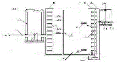
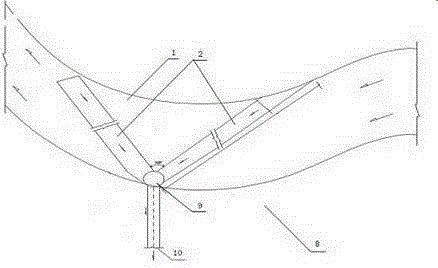
[0036] In northern Shaanxi, river runoff is small and is greatly affected by seasons; the river bed has been dry for a long time, resulting in a large area of floodplain; water intake is difficult and there are often no suitable construction sites for structures. In order to solve this problem, this embodiment provides a seasonal shoal river floodplain type water intake structure, the body is located below the surface of the river channel 1 and the floodplain 8, the body includes the seepage channel 2 and the collection channel connected with the seepage channel 2 A water pipe 4, a seepage canal inlet pipe 11 is embedded in the middle of the seepage canal 2, and a water inlet hole 12 is provided on the seepage canal water inlet pipe 11; And the grit chamber 5 and the water absorption well 6 successively communicated with the water collection well 3 , the bottom of the water absorption well 6 is provided with a submersible sewage pump 7 .
[0037] Its structural diagram is as...
Embodiment 2
[0040] In this embodiment, on the basis of Embodiment 1, the slotting direction of the seepage ditch 2 is parallel to or forms a certain angle with the water flow direction, and the angle is greater than 120°. The setting method of the seepage canal 2 should intercept the whole river course to obtain a larger runoff.
[0041] In this embodiment, the upper part of the water inlet pipe 11 of the seepage ditch is filled with a filter layer. The filter layer is provided with 3-4 layers, each layer is 200-300m thick, the upper surface of the uppermost filter layer is flush with the river bed, and the thickness of each filter layer decreases sequentially from top to bottom, that is, the top is thick and the bottom is thin. The particle size of the material is fine at the top and coarse at the bottom.
[0042] In the present embodiment, the width of the water inlet hole 12 of the water inlet pipe 11 of the seepage ditch is 20mm, such as figure 2 As shown, the length is 3~5 times o...
Embodiment 3
[0044]In this embodiment, on the basis of Embodiment 1 and Embodiment 2, an inspection well 9 is also arranged on the seepage trench 2, and a manhole 13 and a manhole 14 are arranged on the upper surface of the manhole. A ladder 15 is provided in the hole 14 . The maintenance personnel can enter from the manhole 13 and the manhole 14, and go down into the seepage trench by the ladder 15 to carry out maintenance on each equipment.
PUM
 Abstract
Description
Claims
Application Information
 - R&D
- Intellectual Property
- Life Sciences
- Materials
- Tech Scout
- Unparalleled Data Quality
- Higher Quality Content
- 60% Fewer Hallucinations
Browse by: Latest US Patents, China's latest patents, Technical Efficacy Thesaurus, Application Domain, Technology Topic, Popular Technical Reports.
© 2025 PatSnap. All rights reserved.Legal|Privacy policy|Modern Slavery Act Transparency Statement|Sitemap|About US| Contact US: help@patsnap.com


