Restrained brace anti-seismic structure for super high-rise building and manufacturing method

A technology of restrained support and seismic structure, which is applied in the direction of building components, building structures, buildings, etc., can solve the problems of poor seismic capacity and hysteresis performance, and achieve the effects of simple construction, reduced structural cost, and small differences

Active Publication Date: 2015-12-30
CCFED THE FIRST CONSTR & ENG
View PDF7 Cites 4 Cited by
  • Summary
  • Abstract
  • Description
  • Claims
  • Application Information

AI Technical Summary

Problems solved by technology

[0003] The object of the present invention is to provide a super high-rise building constrained braced anti-seismic structure with simple structure, fast construction and good anti-seismic ability, aiming at the problem that the traditional support structure has poor hysteretic performance under repeated loads, resulting in poor anti-seismic ability. Structure and manufacturing method, to overcome the deficiencies in the prior art

Method used


Image

  • Restrained brace anti-seismic structure for super high-rise building and manufacturing method
  • Restrained brace anti-seismic structure for super high-rise building and manufacturing method
  • Restrained brace anti-seismic structure for super high-rise building and manufacturing method

Examples


Embodiment 1

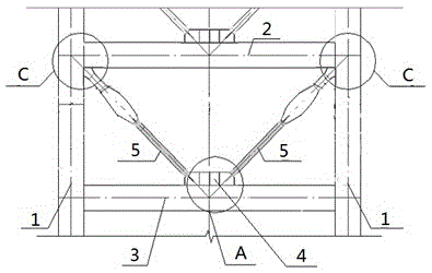
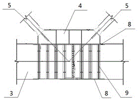
[0021] Such as figure 1 As shown, a kind of super high-rise building constrained braced anti-seismic structure of the present invention, comprises frame column 1 and the upper structural beam 2 and the lower structural beam 3 that are arranged between frame column 1, and the center of lower structural beam 3 is anchored with supporting seat 4. The lower ends of the two support columns 5 are connected and fixed to the support base 4, and the upper ends are respectively supported obliquely at the corners of both sides of the frame column 1 and the upper structural beam 2, forming a V-shaped constrained braced anti-seismic structure. see image 3 , the upper and lower sides of the lower structural beam 3 are provided with embedded steel plates 8, the embedded steel plates 8 on both sides and the I-shaped steel web ribs 9 between them are welded and fixed, and the support seat 4 is welded to the upper embedded steel plate 8 on. see Figure 5 , at the corner of the frame column ...

Embodiment 2

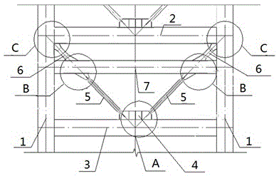
[0024] Such as figure 2 As shown, a kind of super high-rise building constrained braced anti-seismic structure of the present invention, comprises frame column 1 and the upper structural beam 2 and the lower structural beam 3 that are arranged between frame column 1, and the center of lower structural beam 3 is anchored with supporting seat 4. The lower ends of the two support columns 5 are connected and fixed to the support base 4, and the upper ends are respectively supported obliquely at the corners of both sides of the frame column 1 and the upper structural beam 2, forming a V-shaped constrained braced anti-seismic structure. In order to further improve the seismic capacity of the building structure, a middle structural beam 7 connected to the frame column 1 is also arranged between the upper structural beam 2 and the lower structural beam 3, and the upper ends of the two support columns 5 are supported in a V shape on the middle structural beam. 7, and at the same time,...


PUM


Abstract

The invention discloses a restrained brace anti-seismic structure for a super high-rise building and a manufacturing method. The structure comprises frame columns as well as an upper structural beam and a lower structural beam which are arranged between the frame columns, wherein a support seat is anchored at the center of the lower structural beam, the lower ends of two support columns are connected and fixed with the support seat, and the upper ends of the two support columns are respectively and obliquely supported at the corners of two sides of the frame columns and the upper structural beam so as to form a V-shaped restrained brace anti-seismic structure. In order to solve the problems of common brace compression buckling and poor hysteretic behavior, the V-shaped restrained brace anti-seismic structure is arranged in a frame structure, and the structure can comprehensively improve the anti-seismic performance of the whole frame in middle and large earthquakes.

Description

technical field [0001] The invention relates to an anti-seismic structure of constrained supports of a super high-rise building and a manufacturing method thereof, belonging to the technical field of building construction. Background technique [0002] The energy dissipation and shock absorption technology mainly refers to the installation of energy dissipation and shock absorption devices in some parts of the structure, such as interlayer gaps, node joints or joints, or the installation of structural supports, connectors or non-load-bearing shears. Some secondary components such as the force wall are set as energy-dissipating components. When an earthquake comes, these devices or components can provide greater damping for the structure through changes such as friction, plastic deformation, and viscous liquid flow, and consume the input of earthquake motion. energy, reduce the seismic response of the main structure, and thus play a role in protecting the safety of the main s...

Claims


Application Information

Patent Timeline
Patent Type & Authority Applications(China)
IPC IPC(8): E04B1/98E04B1/18E04B1/20E04B1/21
Inventor 王晓磊张明祝国梁洪建伟魏永伟
Owner CCFED THE FIRST CONSTR & ENG
Why Eureka
Try Eureka