An engine transmission mechanism

A technology of transmission mechanism and engine, applied in the direction of machine/engine, mechanical equipment, etc., can solve the problems such as the inability to retain the shape of the cylinder block crankcase, the large error of installation, connection and assembly, to improve convenience, improve power performance, and eliminate dimensional deviations Effect

Active Publication Date: 2018-05-08
李长松
View PDF4 Cites 0 Cited by
  • Summary
  • Abstract
  • Description
  • Claims
  • Application Information

AI Technical Summary

Problems solved by technology

[0008] In order to overcome the above-mentioned defects and deficiencies, the present invention provides an engine transmission mechanism device, which solves the technical problems that the linear motion guide rail engine cannot retain the shape of the cylinder block and crankcase, and the installation, connection, and assembly errors are large.

Method used


Image

  • An engine transmission mechanism
  • An engine transmission mechanism

Examples


Embodiment 1

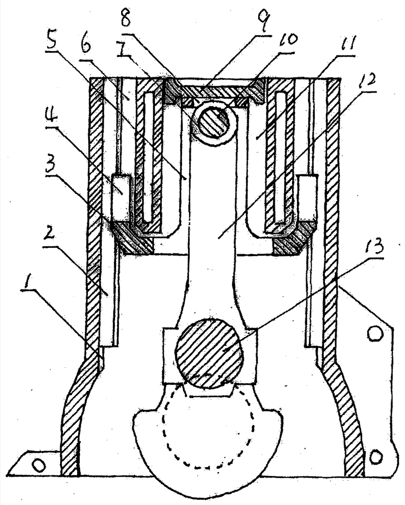
[0022] This example figure 2 As shown, the working principle and specific implementation are as above, the difference is that the slider part is a sliding slider part; The guide rail components form a moving pair; the cylinders are arranged in-line, the diameter of the cylinder is 74mm, the height of the piston is 55mm, and the piston pin seat is reserved. After canceling the piston skirt structure, the piston only retains the 22mm part of the head, and the height of the piston skirt is reduced by 33mm. The cylinder height of 33mm required by the original piston skirt guide, the length of the crank can be increased by 15% on the original basis, and the length of the crank can be increased on the basis of eliminating the friction loss between the original piston and the cylinder due to side pressure Size, increase the piston stroke to improve the power performance of the engine.

Embodiment 2

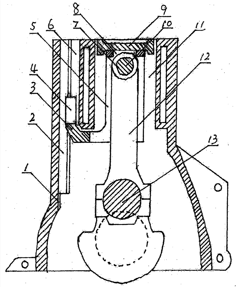
[0024] This embodiment is as described in Embodiment 1, the difference is that the cylinders are arranged in a V shape; the slider part is a rolling slider part; the rolling slider part and the linear motion guide rail part form a moving pair, which is obliquely assembled and fixed on the V-shaped cylinder On the inner walls of both sides, the sliding block is replaced by the sliding block to greatly reduce the friction loss, and further improve the power performance of the engine.


PUM


Abstract

The invention relates to an engine transmission mechanism. The technical scheme is as follows: the side surface of a cylinder is provided with a positioning groove for assembling a rectilinear motion guide rail component; a slipper channel plate bracket is arranged; the slipper channel plate bracket is provided with a slipper component which forms a motion pair with the rectilinear motion guide rail component; the middle of the slipper channel plate bracket is provided with a connecting rod deflection motion groove; the upper end is provided with a piston pin boss circular hole, and the top is provided with a square hole for assembling and fixing the piston; and the connecting rod is respectively connected with the piston pin boss and a crank, thereby forming a novel engine transmission mechanism. Power can be transferred from the slipper component on the slipper channel plate bracket to the gas distribution mechanism, thereby laying the foundation for improving the gas distribution mechanism in future; and the power can be transferred from the piston on the upper end of the slipper channel plate bracket to the crank via the connecting rod, thereby achieving the goals of canceling the piston skirt, reducing the cylinder length dimension required in the original piston skirt guide process, increasing the swing space of the connecting rod, increasing the crank length size, increasing the piston stroke and further enhancing the dynamic performance.

Description

technical field [0001] The invention relates to the technical field of engines, in particular to an engine transmission mechanism device which improves transmission mechanisms and cylinder blocks. Background technique [0002] Traditional gasoline and diesel engines increase the length of the crankshaft and the stroke of the piston, and the length of the cylinder increases accordingly. If the diameter of the cylinder is not increased, the connecting rod will jam the cylinder. Enlarging the piston stroke not only has the technical problem of the connecting rod sticking to the cylinder, but also the friction loss between the piston and the cylinder due to the side pressure restricts the research and development of increasing the piston stroke to improve the engine power performance. [0003] The publication number of the patent bulletin is CN101526029, which discloses a linear motion guide rail engine. Its purpose is to solve the technical problems of friction loss between the...

Claims


Application Information

Patent Timeline
Patent Type & Authority Patents(China)
IPC IPC(8): F02B75/32F02B61/06
Inventor 李长松
Owner 李长松
Why Eureka
Try Eureka