
Air blowing power device

An aerodynamic and airbag technology, applied in the direction of engines, wind engines, machines/engines, etc.

Inactive Publication Date: 2015-12-30
DONGGUANG HUI RU LAI POWER TECH CO LTD
View PDF6 Cites 5 Cited by
  • Summary
  • Abstract
  • Description
  • Claims
  • Application Information

AI Technical Summary

Problems solved by technology

[0003] The present invention aims at the deficiencies of the prior art, and provides an air blowing power device that can improve the operation of the machine

Method used


Image

  • Air blowing power device
  • Air blowing power device
  • Air blowing power device

Examples


Embodiment Construction

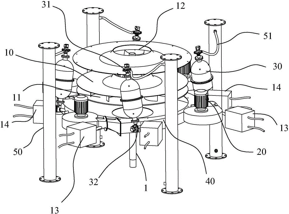
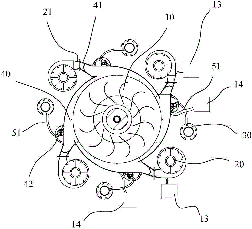
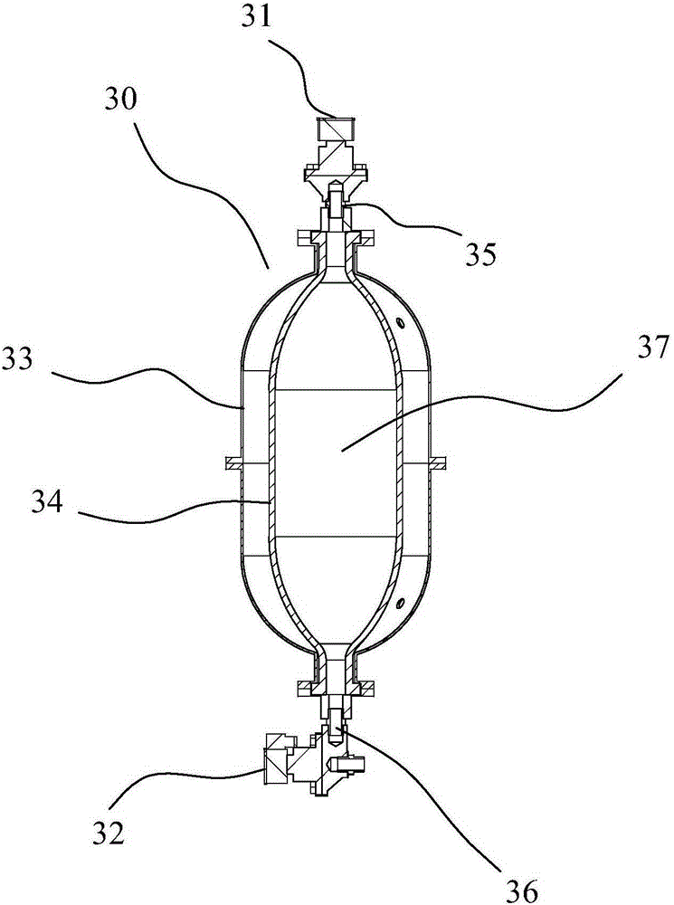
[0028] First, please refer to figure 1 As shown, a blowing power device includes a wind wheel 10, four fans 20 and four jet airbags 30, and guide air ducts 40 respectively corresponding to each fan 20, and the wind wheel 10 is installed on the main shaft of the generator 1, the guide air ducts 40 are arranged around the wind wheel 10, and one end communicates with the air inlet 11 of the wind wheel 10, and the fans 20 are respectively arranged at the other end of the corresponding guide air ducts 40, and pass through The guide air passage 40 blows air to the wind wheel 10, and the air jet bag 30 is provided with an inflation port 31 and an air injection port 32, the inflation port 31 is connected with the inflation device, and the air injection port 32 is connected with the guide air passage 40, and The jetting direction is the same as the airflow direction leading to the air duct 40 , the fan 20 and the jet air bag 30 blow the wind wheel 10 to rotate, and the wind wheel 10 dr...


PUM


Abstract

The invention discloses an air blowing power device. The air blowing power device comprises a main shaft, a wind wheel, a plurality of fans, a plurality of air injection air bags and guide air channels corresponding to the fans respectively. The wind wheel is installed on the main shaft, the guide air channels are formed around the wind wheel, and the fans blow air to the wind wheel through the guide air channels. The air injection air bags are provided with air inflation ports and air injection ports, the air inflation ports are connected with an air inflation device, the air inflation ports are connected with the guide air channels, and the air injection direction is the same with the airflow direction of the guide air channels. The fans and the air injection air bags blow the wind wheel to rotate, and the wind wheel drives the main shaft to rotate. The fans and the air injection air bags blow air to the wind wheel to drive the wind wheel to rotate, then the wind wheel drives the main shaft to rotate, the air blowing power device is suitable for wind generators and guarantees that the wind generators can operate continuously to generate power no matter whether it is windy or breezy, and therefore the requirement for continuous power supply is met.

Description

technical field [0001] The invention relates to the field of power drive technology, in particular to an air blowing power device. Background technique [0002] With the rapid development of the economy, the speed of energy consumption is also accelerating, and energy shortage has become an increasingly serious problem. As a renewable energy, wind energy has attracted more and more attention, and the development of wind energy has become a current energy project. important subject. At present, wind energy is mainly utilized by converting wind energy into electrical energy through wind generators. Existing wind generators are generally inseparable from the windmill impeller to drive the rotor of the generator to rotate to generate electricity. In the natural environment, the wind is often erratic. , not only the wind direction changes from time to time, but also the size of the wind. Due to the structure of the existing windmill, when the wind force is small or light, it is ...

Claims


Application Information

Patent Timeline
IPC IPC(8): F03D9/00F03D11/00
CPCY02E10/72
Inventor 许纯权
Owner DONGGUANG HUI RU LAI POWER TECH CO LTD
Learn More