A swinging rotor compressor

A rotor compressor and rotor technology, applied in the field of rotary compressors, can solve the problems of poor movement of the valve plate, mechanical noise, large resistance loss, etc., and achieve the effect of improved durability and extended service life

Active Publication Date: 2017-08-29
GUANGXI UNIV
View PDF6 Cites 0 Cited by
  • Summary
  • Abstract
  • Description
  • Claims
  • Application Information

AI Technical Summary

Problems solved by technology

The exhaust valve undoubtedly makes the performance of the compressor worse, and the specific performance is as follows: when the air flow passes through the valve, throttling leads to a large resistance loss; the movement of the valve plate causes the air flow to pulsate, resulting in fluid noise; Mechanical noise is produced; when the compressor is controlled by frequency conversion, the movement of the valve plate becomes worse; and the valve plate is the most easily damaged component in the compressor

Method used


Image

  • A swinging rotor compressor
  • A swinging rotor compressor
  • A swinging rotor compressor

Examples


Embodiment Construction

[0023] The present invention will be further described below in conjunction with the accompanying drawings and embodiments.

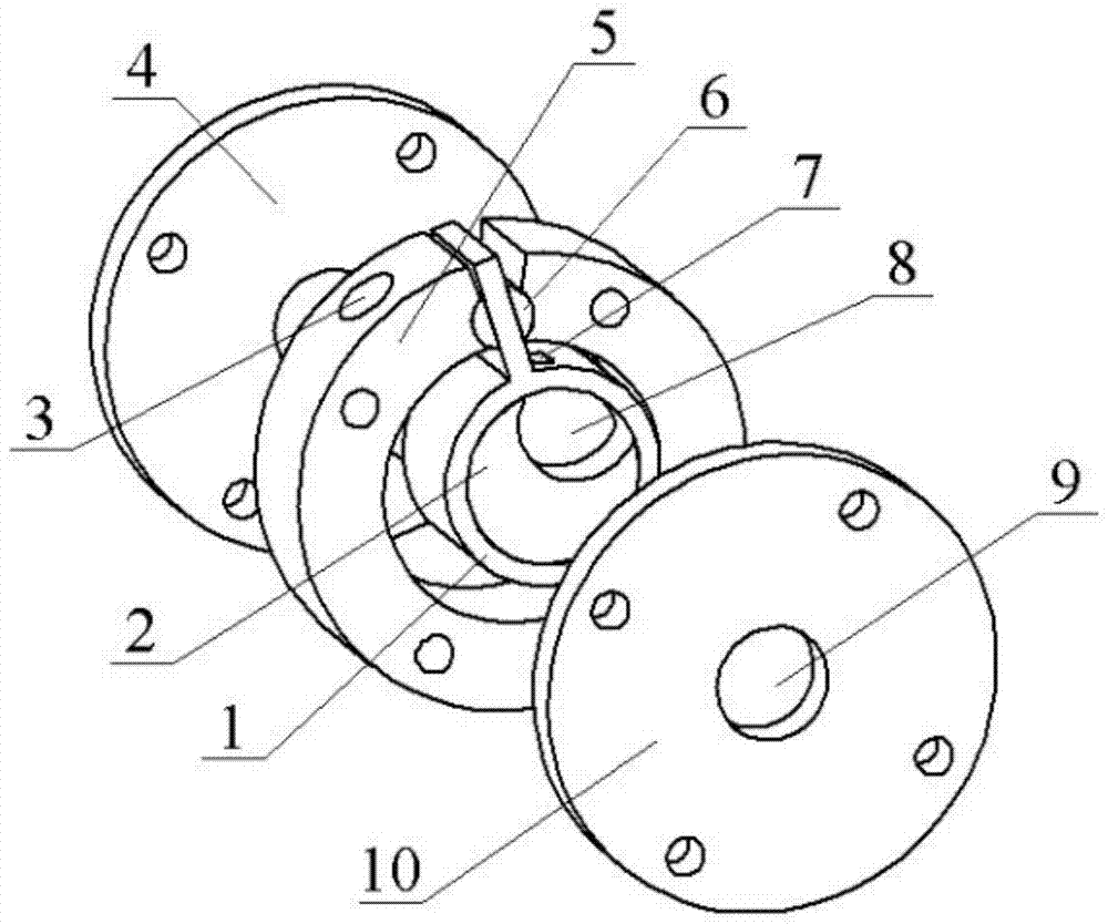
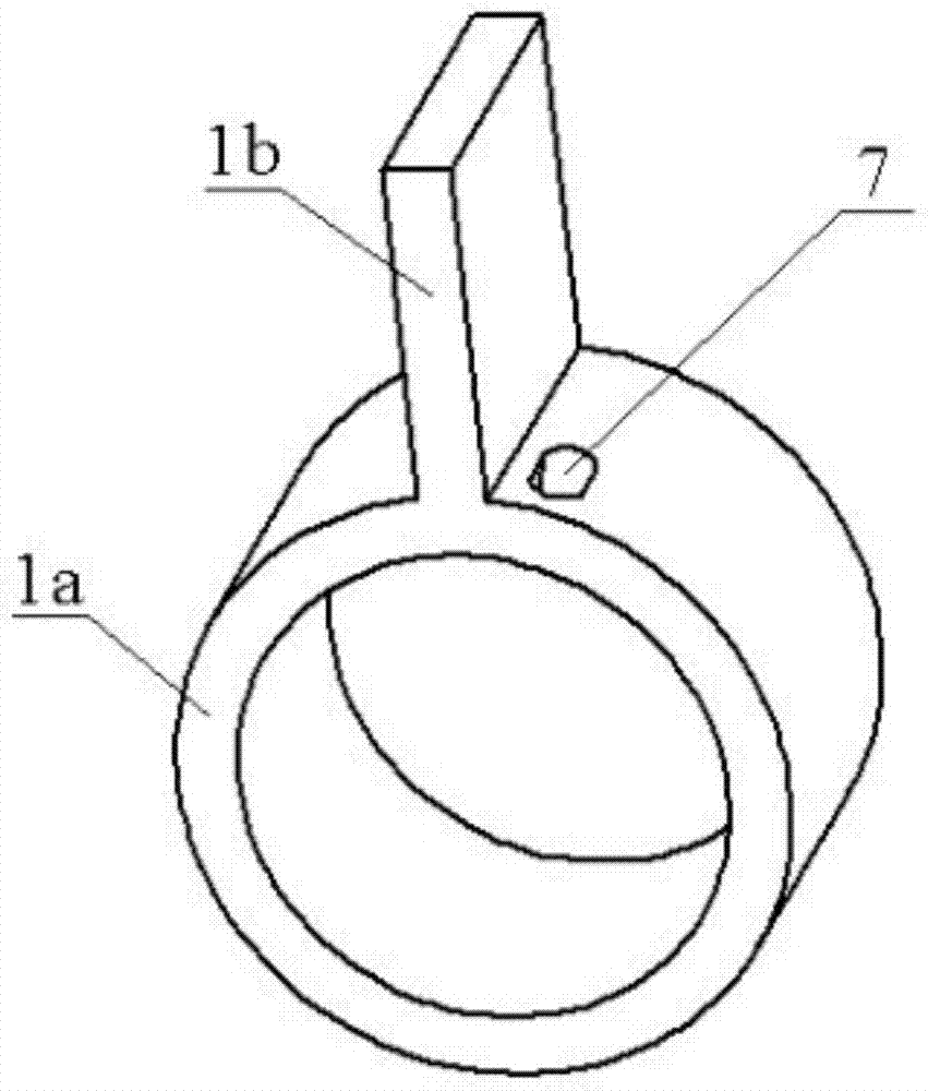
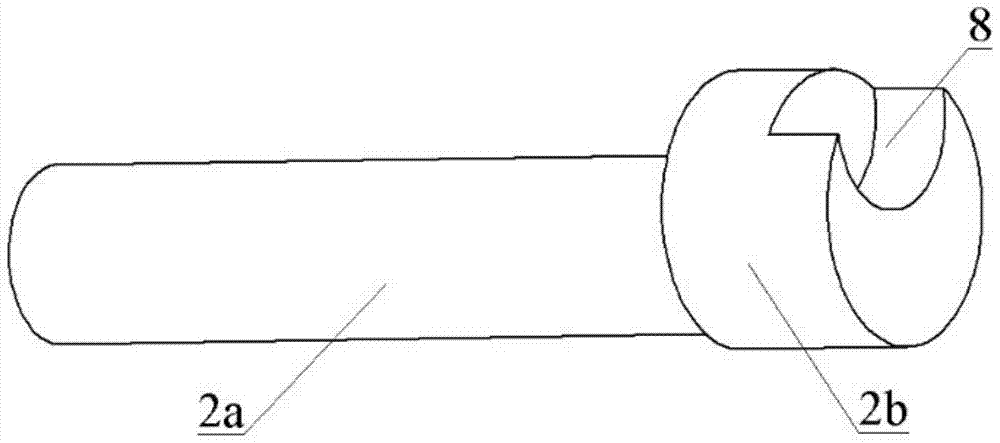
[0024] figure 1 A swing rotor compressor shown includes a swing rotor 1 , an eccentric shaft 2 , a front end cover 4 , a cylinder 5 , a guide rail 6 and a rear end cover 10 . figure 1 The structure of the middle swing rotor 1 is as follows figure 2 , figure 2 The oscillating rotor shown comprises a roller ring 1a and a oscillating link 1b. figure 1 The structure of the center eccentric axle 2 is as follows: image 3 , image 3 The shown eccentric shaft comprises a main shaft 2a and an eccentric 2b.

[0025] figure 1 Among them, the swing rotor 1 is housed in the cylinder 5 . The rolling ring of the oscillating rotor 1 is sleeved on the eccentric wheel of the eccentric shaft 2 , and the main shaft rotation center of the eccentric shaft 2 coincides with the geometric center of the cylinder 5 . The swing rod of the swing rotor 1 can freely slide ...


PUM


Abstract

A swing rotor compressor comprises a swing rotor, an eccentric axle, a front end cover, an air cylinder, a guide rail and a back end cover, wherein the swing rotor comprises a rolling ring and a swing rod; the eccentric axle comprises a spindle and an eccentric wheel; an exhaust hole is formed in the rolling ring and is close to one side of the swing rod; an exhaust cavity is formed in the eccentric wheel and is connected with or disconnected from the exhaust hole in the rolling ring periodically during rotation of the spindle; a flow passing hole is formed in the back end cover, and the exhaust cavity is always communicated with the flow passing hole in the back end cover during rotation of the spindle. No suction valve and exhaust valve are arranged, and compared with a traditional swing rotor compressor, the swing rotor compressor is higher in efficiency, lower in noise and better in speed change characteristic and durability.

Description

technical field [0001] The invention relates to the technical field of rotary compressors, in particular to a swing rotor compressor. Background technique [0002] Rotary compressors are widely used due to their advantages of small size, light weight and simple structure. For example, in room air conditioners, rolling rotor compressors are commonly used. The swing rotor compressor is the twin structure of the rolling rotor compressor. The difference from the rolling rotor compressor structure is that the swing rotor compressor integrates the rolling ring and the swing rod so that there is no sealing and lubrication problem between the two. There is also no need to set a slide spring; after the rolling ring and the swing rod are integrated, the swing rod becomes a support on both sides, which can withstand a large pressure difference; the guide rail can rotate, which reduces the lateral force of the swing rod and eliminates the The friction and wear between the rolling ring ...

Claims


Application Information

Patent Timeline
Patent Type & Authority Patents(China)
IPC IPC(8): F04C21/00
Inventor 潘树林王满潘曦
Owner GUANGXI UNIV
Why Eureka
Try Eureka