

Vibration reduction ring for clutch driven disc
A vibration damping ring and clutch technology, applied in the field of clutches, can solve the problem of rapid wear of the damping ring, and achieve the effects of avoiding rapid wear, reducing contact area and simple structure
Inactive Publication Date: 2015-12-30
WUHU HEFENG CLUTCH
View PDF0 Cites 0 Cited by
- Summary
- Abstract
- Description
- Claims
- Application Information
AI Technical Summary
Problems solved by technology
The surface of the existing damping ring is flat, because the damping ring is sandwiched between the hub and the damping disc, relative friction will be generated during the working process, and the wear of the damping ring is relatively fast
Method used
View moreImage
Smart ImageViewing Examples

Examples
Embodiment Construction
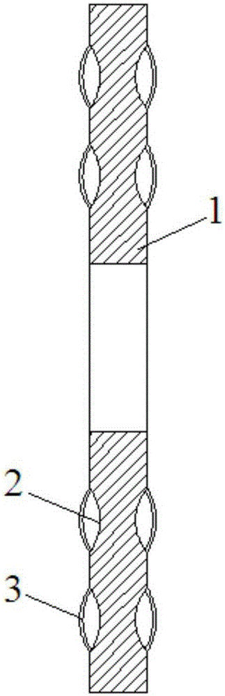
[0010] see figure 1 , a clutch driven disc damping ring, including a damping ring body 1 located between the disc hub and the damping disc, the two sides of the damping ring body 1 are respectively provided with a plurality of grooves 2, located on the same side The grooves are annularly distributed on the surface of the vibration damping ring body, and the notches of the plurality of grooves 2 are respectively installed with arc-shaped elastic sheets 3 that bulge outwards.
[0011] In the present invention, the vibration damping ring body 1 adopts a rubber ring.
Login to View More PUM
 Abstract
The invention discloses a vibration reduction ring for a clutch driven disc. The vibration reduction ring comprises a vibration reduction ring body positioned between a disc hub and a vibration reduction disc; a plurality of grooves are respectively formed in the two side surfaces of the vibration reduction ring body; the grooves positioned in the same side are distributed in the surface of the ring body annularly; outwards protruding arc-shaped elastic pieces are respectively mounted at the groove openings of the grooves. The vibration reduction ring is simple in structure, the arc-shaped elastic pieces play the effect of supporting the disc hub and the vibration reduction disc of the clutch driven disc, contact area between the vibration reduction ring and the disc hub as well as between the disc hub and the vibration reduction disc are reduced to some extent and the fact that the vibration reduction ring is worn more rapidly caused by relative friction is avoided.
Description
technical field [0001] The invention relates to the field of clutches, in particular to a damping ring of a clutch driven plate. Background technique [0002] The driven disc of the clutch is generally provided with a damping ring in the gap between the disc hub and the damping disc. The surface of the existing vibration-damping ring is flat, and since the vibration-damping ring is sandwiched between the disk hub and the vibration-damping disc, relative friction is generated during the working process, and the vibration-damping ring wears quickly. SUMMARY OF THE INVENTION [0003] The purpose of the present invention is to provide a damping ring of a clutch driven disc in order to overcome the defects and deficiencies of the prior art. [0004] The technical scheme of the present invention is as follows: [0005] A damping ring of a clutch driven disc, comprising a damping ring body located between a disc hub and a damping disc, characterized in that: the two sides of th...
Claims
Login to View More Application Information
Patent Timeline
 IPC IPC(8): F16D13/58F16F15/10
Inventor许道生
OwnerWUHU HEFENG CLUTCH