Fuel nozzle and combustion chamber

A technology of fuel nozzles and nozzles, which is applied in the field of aero-engines to achieve the effects of improving heat transfer performance, reducing local irregularities, and improving working stability

Active Publication Date: 2017-10-20
AECC COMML AIRCRAFT ENGINE CO LTD
View PDF1 Cites 0 Cited by
  • Summary
  • Abstract
  • Description
  • Claims
  • Application Information

AI Technical Summary

Problems solved by technology

[0007] The inventors have found that there are at least the following problems in the prior art: the combustion chamber needs to have a good aerodynamic basic design and deal with the local irregularities of the air flow so as to ensure the uniform velocity of the air flow before entering the combustion chamber flame tube distributed
However, the existing technology cannot meet the above requirements

Method used


Image

  • Fuel nozzle and combustion chamber
  • Fuel nozzle and combustion chamber
  • Fuel nozzle and combustion chamber

Examples


Embodiment Construction

[0064] Combine below Figure 1 to Figure 7 A more detailed elaboration of the technical solution provided by the present invention, a technical solution obtained by replacing any technical means provided by the present invention or combining any two or more technical means or technical features provided by the present invention with each other All should be within the protection scope of the present invention.

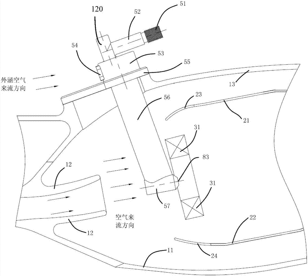
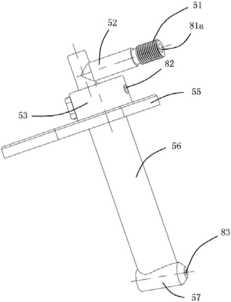
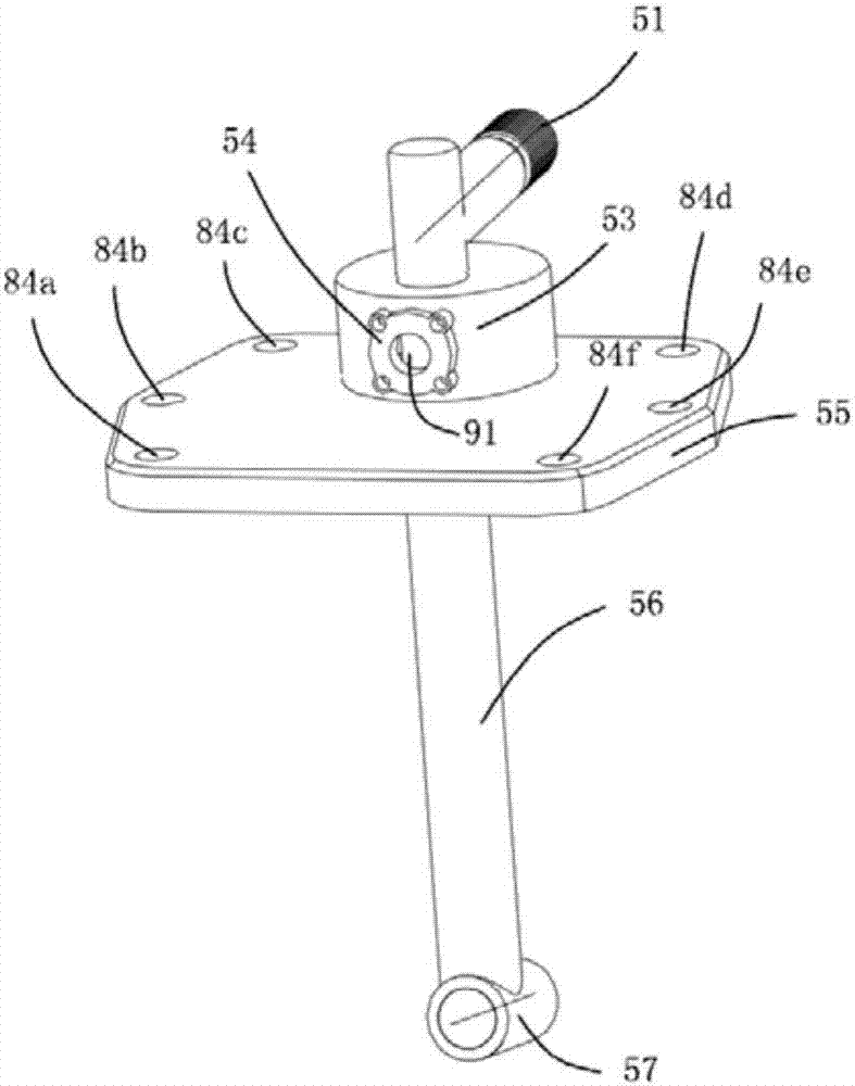
[0065] An embodiment of the present invention provides a fuel nozzle, which includes a nozzle inlet portion 120 , a fuel injection rod body 101 , a nozzle head 57 and a decompression housing 56 . The nozzle inlet 120 and the nozzle head 57 are respectively fixed on the two ends of the fuel injection rod body 101; the decompression cover 56 surrounds the outside of the fuel injection rod body 101, and the decompression cover 56 is connected with the nozzle inlet 120 and the fuel injection rod body 101. And at least one of them in the nozzle head 57 is fixed. In this e...


PUM


Abstract

The invention discloses a fuel nozzle and a combustion chamber, which relate to the field of aero-engines and are used for reducing the influence of the fuel nozzle on the irregularity of the air flow in the combustion chamber. The fuel nozzle includes a nozzle inlet, a fuel injection rod body, a nozzle head and a decompression housing; the nozzle inlet and the nozzle head are respectively fixed at both ends of the fuel injection rod rod; the decompression housing surrounds the outside of the fuel injection rod rod , the decompression cover is fixed to at least one of the nozzle inlet, the fuel injection rod body and the nozzle head; wherein, under the same conditions, the air resistance of the decompression cover is smaller than the air resistance of the fuel injection rod body . In the above technical solution, the structure of the decompression outer cover has a weakening effect on the local irregularity of the airflow in the combustion chamber, and the air flow resistance loss of the air flowing through the decompression outer cover is small, which reduces the local irregularity of the inlet air in front of the flame tube and improves the Uniformity of air flow in the combustion chamber.

Description

technical field [0001] The invention relates to the field of aero-engines, in particular to a fuel nozzle and a combustion chamber. Background technique [0002] Nowadays, the combustors of aero-engines mostly adopt the straight-flow short annular combustor structure, and the work of the annular combustor is sensitive to the inlet flow field generated by the inlet airflow, and a bad inlet flow field will affect the flow field distribution at the outlet of the combustor. This is very unfavorable to follow-up structures such as the working state and life of the turbine. After entering the combustion chamber from the compressor, the airflow enters the head of the combustion chamber and the flame tube respectively, and the structure of the head of the combustion chamber is one of the most important structures of the entire combustion chamber. The airflow entering it will affect the working state of the entire combustion chamber, and One of the biggest influences on inlet airflo...

Claims


Application Information

Patent Timeline
Patent Type & Authority Patents(China)
IPC IPC(8): F23R3/28
Inventor 胡莹超汪好郭德三刘雯佳李彬
Owner AECC COMML AIRCRAFT ENGINE CO LTD
Why Eureka
Try Eureka