Reverse flow type spiral baffle plate U-shaped pipe bundle heat exchanger

A technology of spiral baffles and baffles, applied in the direction of heat exchanger types, heat exchanger shells, indirect heat exchangers, etc., can solve the problems of ignoring pipe penetration, achieve the effect of easy installation and fixation, and suppress reverse leakage

Active Publication Date: 2015-12-30
SOUTHEAST UNIV
View PDF5 Cites 4 Cited by
  • Summary
  • Abstract
  • Description
  • Claims
  • Application Information

AI Technical Summary

Problems solved by technology

But this invention has ignored the problem of how to realize the pipe penetration

Method used


Image

  • Reverse flow type spiral baffle plate U-shaped pipe bundle heat exchanger
  • Reverse flow type spiral baffle plate U-shaped pipe bundle heat exchanger
  • Reverse flow type spiral baffle plate U-shaped pipe bundle heat exchanger

Examples


Embodiment

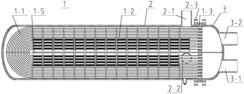
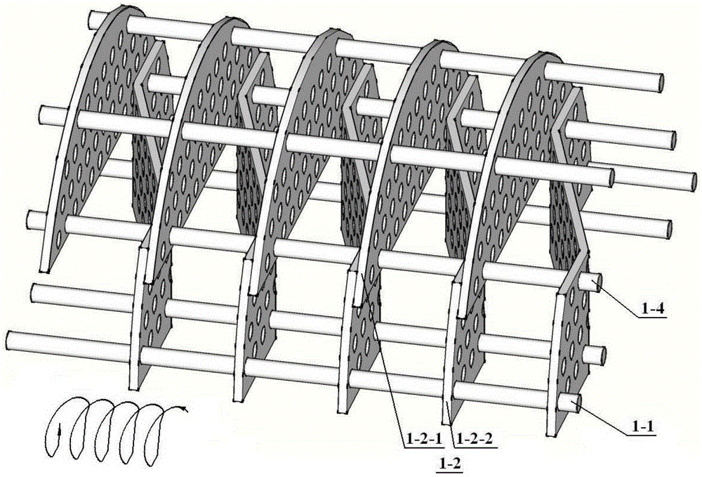
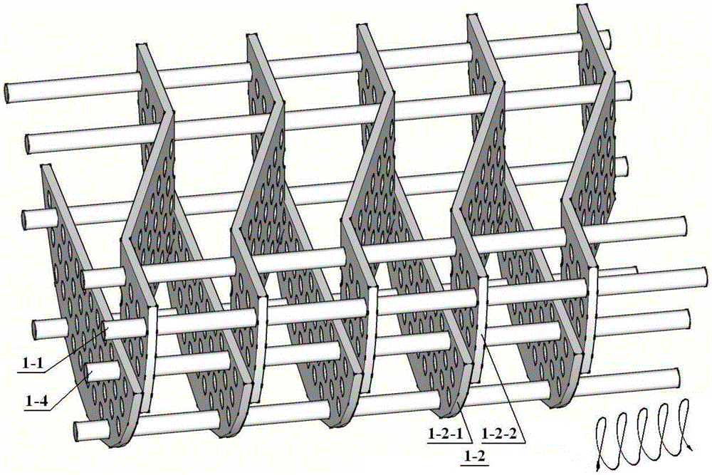
[0019] A counterflow spiral baffle U-shaped tube bundle heat exchanger, composed of a U-shaped tube bundle core 1, a shell 2 with flanges 2-3 and a water chamber 3; the shell 2 is close to the flange 2 -3 The inlet 2-1 of the shell side fluid and the outlet 2-2 of the shell side fluid are respectively arranged on the upper and lower half cylinders at one end, the water chamber 3 is divided into upper and lower spaces, and the water The outlet 3-2 of the tube side fluid and the inlet 3-1 of the tube side fluid are respectively arranged on the head of the chamber 3; the U-shaped tube bundle core 1 is composed of a U-shaped tube bundle 1-1 and a spiral baffle assembly 1-2 , tube plate 1-3, pull rod casing assembly 1-4, and longitudinal partition plate 1-5; one end of the longitudinal partition plate 1-5 in the length direction is connected to the tube plate, and the other end is close to the U-shaped tube bundle bend The pipe section is provided with sealing strips on both sides ...


PUM


Abstract

A reverse flow type spiral baffle plate U-shaped pipe bundle heat exchanger is composed of a U-shaped pipe bundle core body, a shell and a water chamber. The U-shaped pipe bundle core body is composed of a U-shaped pipe bundle, spiral baffle plate assemblies, pipe plates, pull rod sleeve assemblies and longitudinal partition plates. The upper cylindrical area and the lower cylindrical area of each spiral baffle plate assembly are each composed of a flat plate round-notch-shaped baffle plate and an arc end strip-shaped baffle plate. Each arc end strip-shaped baffle plate is composed of an inclined section, a left bent flat section and a right bent flat section. Every two corresponding baffle plates are provided with an overlapped area of a row of pipes. The structural limitation that ordinary spiral baffle plates can hardly be arranged in semi-cylindrical spaces and numerous defects of arch baffle plate heat exchangers can be overcome, the purpose of arranging spiral baffle plate passageways in a semi-cylindrical space to obtain the reverse flow type U-shaped pipe bundle heat exchanger is achieved, and the reverse flow type spiral baffle plate U-shaped pipe bundle heat exchanger has the advantages of being high in heat conduction coefficient, low in flowing resistance, and the like.

Description

technical field [0001] The invention relates to a U-shaped tube bundle heat exchanger, in particular to a U-shaped tube bundle heat exchanger with a counterflow spiral baffle. Background technique [0002] U-shaped tube bundle heat exchanger is the main form of high temperature and high pressure heat exchanger. For example, the feedwater heater with U-shaped tube bundle is an important equipment in the power plant system. In particular, the high-pressure heater also has a built-in superheated steam cooling section and a drain cooling section in addition to the steam condensation section. Because the steam cooling section in the feedwater heater The cooling section and the hydrophobic cooling section are respectively located at the inlet and outlet sections of the U-shaped tube bundle, so countercurrent heat exchange must be performed. Most of the structures currently used are bow-shaped baffle channels, which have defects such as flow dead zone, low heat transfer coefficien...

Claims


Application Information

Patent Timeline
Patent Type & Authority Applications(China)
IPC IPC(8): F28D7/06F28F9/24
Inventor 陈亚平王明超吴嘉峰
Owner SOUTHEAST UNIV
Why Eureka
Try Eureka