Wrong-inserting preventing speed sensor

A speed sensor and anti-insertion technology, which is applied to devices using electric/magnetic methods, etc., can solve the problem of lack of anti-insertion function, etc., and achieve the effect of low manufacturing cost and satisfying use requirements.

Inactive Publication Date: 2015-12-30
XIAN AVIATION BRAKE TECH
View PDF6 Cites 2 Cited by
  • Summary
  • Abstract
  • Description
  • Claims
  • Application Information

AI Technical Summary

Problems solved by technology

Patent No. after inquiry: CN201210002176.1 The principle of the wheel speed sensor in the double-section four-redundancy wheel speed sensor is the same as the present invention, but it does not have the function of preventing wrong insertion; Patent No.: CN1725017 Rotation sensor, sensor and wheel hinge The method is the transmission shaft connection, the installation method is simpler than the present invention, and does not have the function of preventing wrong insertion

Method used


Image

  • Wrong-inserting preventing speed sensor
  • Wrong-inserting preventing speed sensor
  • Wrong-inserting preventing speed sensor

Examples


Embodiment Construction

[0021] This embodiment is an anti-misplug speed sensor.

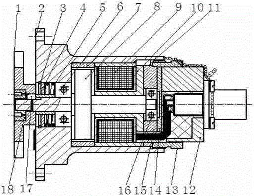
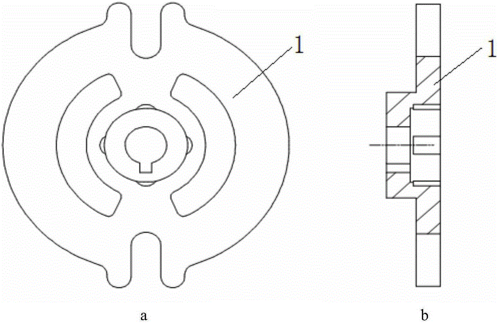
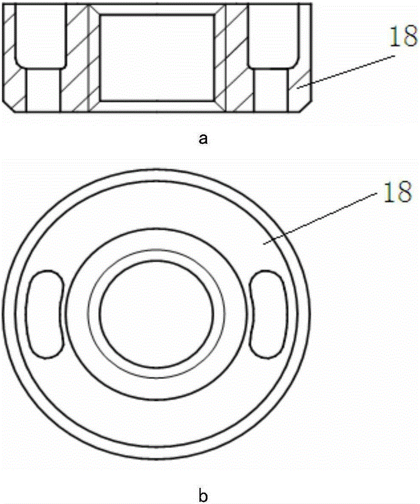
[0022] This embodiment includes an anti-wrong insertion fork 1, a housing 2, a circlip 3 for holes, a dustproof ring 4, a spring 5, a large bearing 6, a gear ring 7, a rotor assembly 8, a coil assembly 9, a magnetizer 10, Straight pin 11, base 12, screw sleeve 13, compression cover 14, bearing seat 15, small bearing 16, key 17, lock nut 18.

[0023] In this embodiment: the large bearing 6 is pressed into the positioning boss in the middle of the rotor assembly 8, the coil assembly 9 and the magnetizer 10 are installed on the rotor assembly 8, and the small bearing 16 is pressed into the runner located in the rotor assembly 8 Install the shaft on the end face, put the gear ring 7 and the rotor assembly 8 equipped with the coil assembly 9, the magnetizer 10, the large bearing 6 and the small bearing 16 into the housing 2, and then put it into the bearing seat 15, and at the same time press the Cover 14 compresses bearing...


PUM


Abstract

The invention discloses a wrong-inserting preventing speed sensor. A large bearing is located in the middle of a rotor assembly. A coil assembly and a magnetic conductor are installed on the rotor assembly. A small bearing is installed in an installation shaft of the rotor assembly. The magnetic conductor, a bearing pedestal, a gear ring and the rotor assembly are installed in a shell. A spring and a dust-proof ring are arranged on a rotating shaft of the rotor assembly in a sleeving mode and locate in a cavity in one end of the shell. A wrong-inserting preventing shifting fork is located on the outer side of the shell, fixed to the rotating shaft of the rotor assembly in a sleeving mode and located at the end provided with the spring. The end face of the rotating shaft is provided with a locking nut for fastening the wrong-inserting preventing shifting fork. The rotating shaft of the rotor assembly is in clearance fit with the wrong-inserting preventing shifting fork. A shifting rod carries out transmission in a shifting fork groove, and has the wrong-inserting preventing function. Installation test flight verifies that the shifting rod is installed free of displacement or disengagement in the test flight process.

Description

technical field [0001] The invention relates to the field of aircraft electronic anti-skid braking systems, in particular to an anti-wrong insertion structure of a speed sensor. Background technique [0002] As the research and application of electronic anti-skid braking system technology becomes more and more mature, the system is installed in most aircrafts at present. As an important part of the electronic anti-skid braking system, the speed sensor provides the control box with a sinusoidal alternating voltage whose frequency is proportional to the angular velocity of the wheel. Signal for the electronic anti-skid brake system to detect the wheel speed. During the actual installation process of the traditional speed sensor, the transmission pin on the wheel end cover assembly may be installed outside the installation slot of the wheel speed sensor shift fork. In actual installation, the measurement signal of the speed sensor may be inaccurate and cause the brake Faults a...

Claims


Application Information

Patent Timeline
Patent Type & Authority Applications(China)
IPC IPC(8): G01P3/48
Inventor 张驰马晓军赵燕明亢敏
Owner XIAN AVIATION BRAKE TECH
Why Eureka
Try Eureka