Indoor dual-polarization omnibearing ceiling antenna

A ceiling-mounted antenna and vertically polarized antenna technology, which is applied to antenna unit combinations, antennas, antenna arrays and other directions with different polarization directions, can solve the problems such as the inability of cells to reflect the MIMO effect and inconsistent coverage, and improve spectrum utilization. rate, consistent coverage, and good coverage

Inactive Publication Date: 2015-12-30
CHINA TOWER CO LTD
View PDF4 Cites 17 Cited by
  • Summary
  • Abstract
  • Description
  • Claims
  • Application Information

AI Technical Summary

Problems solved by technology

[0008] 2. Due to the different structures of the vertical polarization unit and the horizontal polarization unit, such as figure 2 As shown, the coverage of th

Method used


Image

  • Indoor dual-polarization omnibearing ceiling antenna
  • Indoor dual-polarization omnibearing ceiling antenna
  • Indoor dual-polarization omnibearing ceiling antenna

Examples


Embodiment Construction

[0051] In order to make the technical problems, technical solutions, and advantages to be solved by the embodiments of the present invention clearer, a detailed description will be given below with reference to the drawings and specific embodiments.

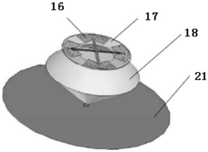
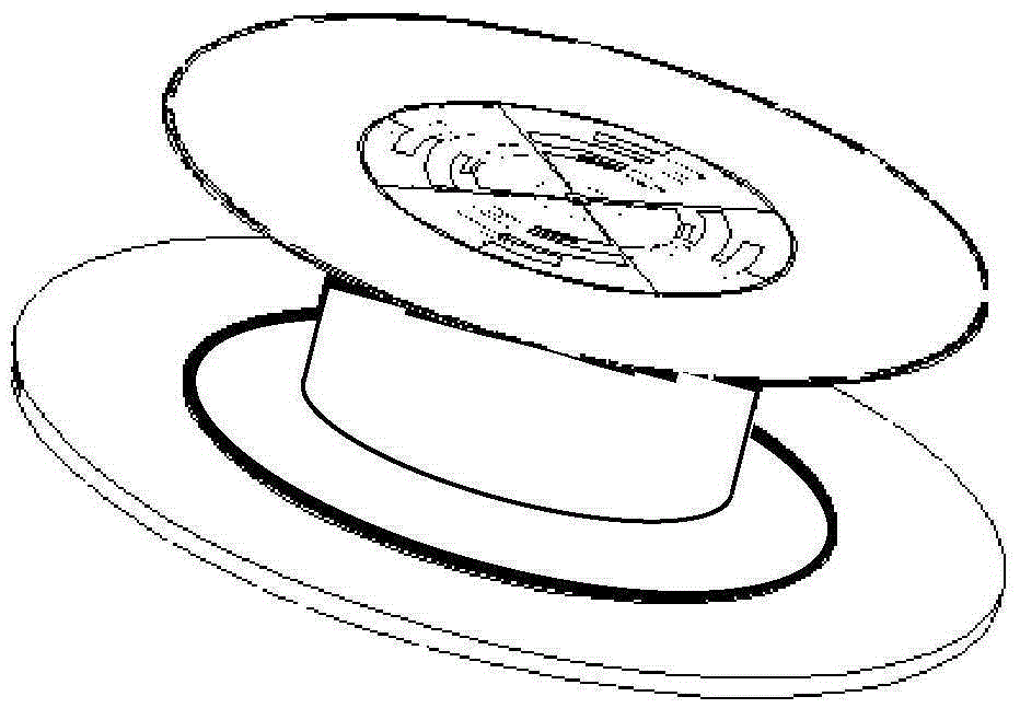
[0052] The embodiment of the present invention provides an indoor dual-polarized omni-directional ceiling antenna to solve the problem that the working frequency of the vertically polarized antenna and the horizontally polarized antenna in the prior art are consistent, and the coverage of the two polarization directions is consistent. Figure 3A , 3B , 4, and 10, the antenna includes a vertically polarized antenna and a horizontally polarized antenna, and the horizontally polarized antenna is placed horizontally above the vertically polarized antenna and does not touch each other; the horizontally polarized antenna The antenna includes a dielectric plate 6, two circular ring arrays positioned axisymmetrically on the top and bottom sur...


PUM


Abstract

The invention provides an indoor dual-polarization omnibearing ceiling antenna which comprises a perpendicular polarization antenna body and a horizontal polarization antenna body arranged above the perpendicular polarization antenna body. The horizontal polarization antenna body comprises a dielectric slab, two axisymmetric annular arrays located on the top face and the bottom face of the dielectric slab, and a first cable. The annular arrays comprise low-frequency radiation unit sets and high-frequency radiation unit sets located on the inner sides of the low-frequency radiation unit sets. Each low-frequency radiation unit in each low-frequency radiation unit set is connected with a high-frequency radiation unit at the corresponding position in the corresponding high-frequency radiation unit set through a circuit, so that a plurality of subarrays are formed, and the subarrays on the same side of the dielectric slab are connected in parallel. The subarrays on the top face of the dielectric slab are connected in parallel and then connected with an inner conductor of the first cable, and the subarrays on the bottom face of the dielectric slab are connected in parallel and then connected with an outer conductor of the first cable. According to the indoor dual-polarization omnibearing ceiling antenna, a uniform current loop is simulated, so that omnibearing radiation is achieved, and thus working frequency of the perpendicular polarization antenna body coincides with that of the horizontal polarization antenna body.

Description

Technical field [0001] The invention relates to the technical field of mobile communication, in particular to an indoor dual-polarization omnidirectional ceiling antenna. Background technique [0002] The MIMO (Multiple Input Multiple Output) technology of the mobile communication indoor distribution system can make full use of space resources, and realize multiple transmission and multiple reception through multiple antennas. Without increasing the spectrum resources and antenna transmission power, the system can be doubled. Channel capacity and significantly improve communication quality are regarded as the core technology of next-generation mobile communication. [0003] The indoor distribution system antenna is an important part of the mobile communication indoor distribution system, and its performance directly affects the communication quality of the indoor distribution system. Common indoor distributed system antennas can be divided into single-polarized omnidirectional cei...

Claims


Application Information

Patent Timeline
IPC IPC(8): H01Q21/00H01Q21/24H01Q1/38H01Q1/50H01Q1/48H01Q5/10H01Q5/42
Inventor 窦笠李新中邹勇李娟薛楠
Owner CHINA TOWER CO LTD
Why Eureka
Try Eureka