Lead wire cover and mounting method thereof

A lead-out and installation port technology, applied in the direction of electromechanical devices, casings/covers/supports, electrical components, etc., can solve problems such as unfavorable welding operations, narrow space for lead-out covers, and screws are easy to fall off, to avoid strength. Insufficient, ensuring sealing, and facilitating the effect of assembly and positioning

Active Publication Date: 2015-12-30
GREE ELECTRIC APPLIANCES INC +1
View PDF6 Cites 3 Cited by
  • Summary
  • Abstract
  • Description
  • Claims
  • Application Information

AI Technical Summary

Problems solved by technology

[0005] (1) The lead-out wire cover is generally made of plastic material, and the power connector is fixed on the lead-out wire cover with screws, so there is a hidden danger that the lead-out wire cover is not strong enough and the screws are easy to fall off;
[0006] (2) Since the lead-out wire of the power supply is welded to the terminal of the power connector, the lead-out wire of the power supply must first be penetrated into the lead-out wire cover and then welded. Since the space in the lead-out wire cover is narrow, it is not conducive to the operation of welding, which increases the The complexity of welding

Method used


Image

  • Lead wire cover and mounting method thereof
  • Lead wire cover and mounting method thereof
  • Lead wire cover and mounting method thereof

Examples


Embodiment 1

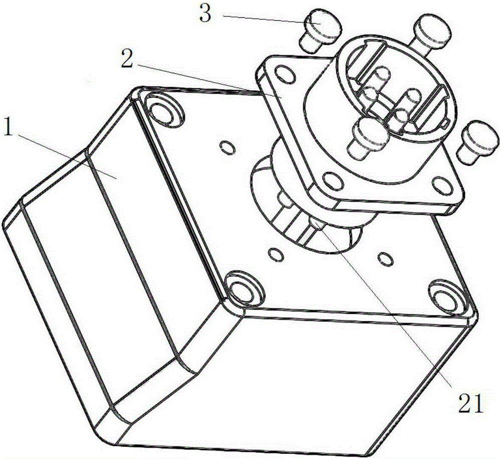
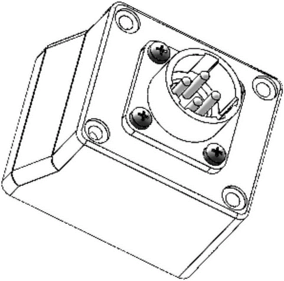
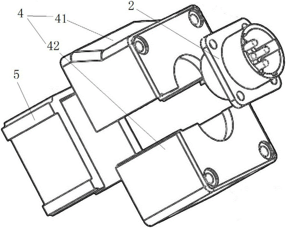
[0042] This embodiment provides a lead-out cover, which is used to install the power connector on the motor, such as Figure 3 to Figure 5 As shown, the lead wire cover of this embodiment includes a cover body 4 and a fixing frame 5 . Wherein, an installation opening for installing the power connector 2 is opened on the cover body 4 , and the installation opening communicates with the accommodating space in the cover body 4 . The fixing frame 5 is arranged in the cover body 4 and cooperates with the cover body to fix and install the power connector 2 on the lead wire cover.

[0043] The lead-out cover provided in this embodiment does not need to use screws to fix the power connector on the lead-out cover, and the power connector can be fixed on the lead-out cover only through the cooperation of the fixing frame and the cover, thus avoiding the need for prior art Due to the use of screws to fix, there is a hidden danger that the strength of the lead-out cover is insufficient a...

Embodiment 2

[0054] Preferably, this embodiment provides a lead wire cover. On the basis of the above embodiments, the cover body 4 in the lead wire cover of this embodiment is formed by connecting at least two parts. Wherein, when at least two parts are connected together, an installation opening as described above is formed at the joint. Preferably, the cover body 4 of this embodiment is formed by connecting the first part 41 and the second part 42, such as Figure 3-7 shown.

[0055] The cover body of the lead wire cover provided in this embodiment adopts a split structure (that is, consists of at least two parts), so that when the motor lead wire is welded, it is not necessary to pass the motor lead wire through the lead wire cover in advance, and then connect to the power supply Weld the terminals of the power connector; but only directly weld the lead wires of the motor and the terminals of the power connector, then assemble the lead wire cover with the power connector, and finally ...


PUM


Abstract

The invention relates to a lead wire cover. The lead wire cover is used for mounting a power connector on a motor; a lead wire of the motor is connected with a connecting terminal of the power connector; the lead wire cover comprises a cover body and a fixing rack, wherein a mounting opening for mounting the power connector is formed in the cover body, and communicated with an accommodating space in the cover body; the fixing rack is arranged in the cover body, and used for fixing the power connector mounted on the cover body. According to the lead wire cover provided by the invention, using a bolt to fix the power connector is eliminated, and potential hazards that the strength of the lead wire cover becomes insufficient due to fixing through the bolt, and the bolt is likely to fall off are prevented; in addition, through the adoption of the lead wire cover, an operator can conveniently weld the motor lead wire and the connecting terminal on the power connector.

Description

technical field [0001] The invention relates to the technical field of motors, in particular to a lead wire cover and an installation method thereof. Background technique [0002] Servo motors with higher power need to use power connectors, so it is necessary to use the power lead-out cover to install the power connectors on the servo motor. [0003] figure 1 It is an exploded schematic diagram of the structure of the lead-out cover and the power connector in the prior art, figure 2 It is a schematic diagram of the overall assembly of the lead-out cover and the power connector in the prior art, such as figure 1 , figure 2 As shown, the power connector 2 needs to be installed on the lead-out cover 1 with screws 3, and the terminal 21 on the power connector 2 needs to be welded with the motor power lead-out wire passing through the lead-out cover. Finally, the lead wire cover 1 is fixed on the casing of the servo motor by screws. [0004] However, the inventors of the p...

Claims


Application Information

Patent Timeline
Patent Type & Authority Applications(China)
IPC IPC(8): H02K5/22
Inventor 郝福刚李昊钟成堡焦雷李峰岩
Owner GREE ELECTRIC APPLIANCES INC
Why Eureka
Try Eureka