Pallet for printed-circuit board wave-soldering furnaces

A printed circuit board and wave soldering technology, which is used in printed circuits, printed circuit manufacturing, and assembling printed circuits with electrical components. The effect of adjusting the time of the wave soldering track, reducing the storage space and management difficulty, and reducing the production cycle and cost

Active Publication Date: 2015-12-09
WASION GROUP HLDG
View PDF6 Cites 2 Cited by
  • Summary
  • Abstract
  • Description
  • Claims
  • Application Information

AI Technical Summary

Problems solved by technology

The use of special trays has the following disadvantages: 1. The production cycle of the tray is long and the cost is high; 2. Since each printed circuit board needs a special tray, the storage capacity of the tray is large, and special personnel are required to manage the tray and store it.
There are the following disadvantages in the use of selective wave soldering: 1. Selective wave soldering is an emerging technology, the technology is not mature enough, and the use is unstable; 2. A large amount of capital investment is required to replace wave soldering equipment; 3. Each printed circuit board needs to correspond to one Plan, when a new product is put into production, it takes a long time to make the plan

Method used


Image

  • Pallet for printed-circuit board wave-soldering furnaces
  • Pallet for printed-circuit board wave-soldering furnaces
  • Pallet for printed-circuit board wave-soldering furnaces

Examples


Embodiment Construction

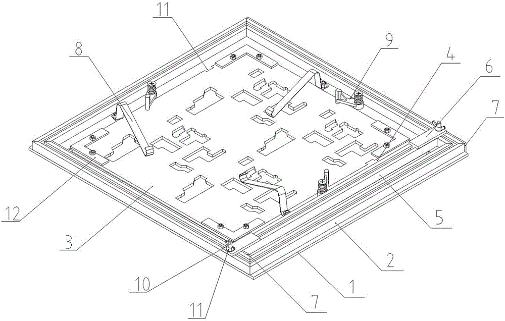
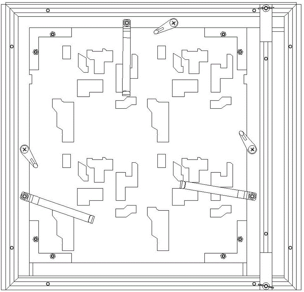
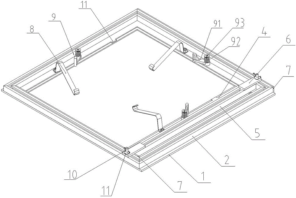
[0024] Such as Figure 1 to Figure 3 As shown, this embodiment discloses a printed circuit board wave soldering furnace tray, including a main rectangular bottom plate 1, a rectangular vertical frame 2, a special bottom plate 3, a moving bottom plate 4, a moving bracket 5, a fixed block 6, and a synthetic stone Article 7, printed circuit board buckle 8, special bottom plate buckle assembly 9.

[0025] The rectangular vertical frame 2 is surrounded by profiles with T-shaped grooves along the length direction, and each profile is arranged with the opening of the T-shaped groove facing upwards, and synthetic stone strips 7 of corresponding sizes are respectively installed on the inner wall and outer wall of the profile on one opposite side.

[0026] A rectangular hole is opened on the rectangular bottom plate 1, and the rectangular upright frame 2 is connected to the upper surface of the rectangular bottom plate 1 and the periphery of the rectangular hole. The widths of the soli...


PUM


Abstract

The present invention discloses a pallet for printed-circuit board wave-soldering furnaces including a rectangular bottom plate, a rectangular vertical frame and a rectangular special purpose bottom plate. The rectangular bottom plate is provided with a rectangular hole, the rectangular vertical frame connects the upper surface of the rectangular bottom plate and the periphery of the rectangular hole, the special purpose bottom plate is assembled in the rectangular hole of the rectangular bottom plate, and a printed-circuit board is arranged on the special purpose bottom plate and is fixed on the special purpose bottom plate through a limiting stopper and a printed-circuit board pressing buckle. The plan view size of the special purpose bottom plate is less than the size of the rectangular hole of the rectangular bottom plate, and a size adjusting component is connected between a pair of opposite edges of the rectangular vertical frame. The size adjusting component includes a movable bottom plate and a sliding holder, wherein, the sliding holder is connected to the upper side of the movable bottom plate so as to move in the rectangular hole of the rectangular bottom plate by the cooperation of the corresponding edge of the special purpose bottom plate. One pallet is suitable for printed-circuit boards with various sizes. The special purpose bottom plate can be adjusted according to various plate types, and a production department is only required to manage and store the special purpose bottom plate so that the storage space and the management difficulty are greatly reduced, the pallet production cycle is shortened and the pallet production cost is saved.

Description

technical field [0001] The invention relates to a plug-in wave soldering tooling in an electronic assembly process, in particular to a pallet for wave soldering. Background technique [0002] With the rapid development of science and technology, electronic components and printed circuit board technology are also developing in the direction of miniaturization and integration. Product design pays more and more attention to customer experience, and "Industry 4.0" even proposes a personalized and customized production method, which leads to rapid product replacement and a wide variety of products. This puts forward higher requirements for electronic assembly. SMT (Surface Mount Technology) is developing rapidly, and the placement rate of circuit boards is getting higher and higher, but there are still many high-power components that cannot be mounted by SMT and require plug-ins and wave soldering. The wave soldering of the printed circuit board needs to protect the SMT compone...

Claims


Application Information

Patent Timeline
Patent Type & Authority Applications(China)
IPC IPC(8): H05K3/34
CPCH05K3/34H05K2203/0165
Inventor 崔向欢朱江周奇李茂徐哲廖前忠
Owner WASION GROUP HLDG
Why Eureka
Try Eureka