Combined generator

A generator and composite technology, applied in the direction of electrical components, electromechanical devices, electric components, etc., can solve the problem of long installation distance between water turbine or steam engine and generator, inability to make full use of water or steam impact energy, and incomplete transmission of kinetic energy and other problems, to achieve the effects of avoiding current leakage, compact structure, and full power utilization

Inactive Publication Date: 2015-12-30
刘运念
View PDF5 Cites 2 Cited by
  • Summary
  • Abstract
  • Description
  • Claims
  • Application Information

AI Technical Summary

Problems solved by technology

[0002] Existing generators generally use a water turbine or a steam engine to drive the generator rotor to generate electricity, but this type of generator consumes a lot of power, and the distance between the water turbine or steam engine and the generator is relatively long, and the kinetic energy between the water turbine or steam turbine and the generator The transmission is incomplete, and the impact energy of water or steam cannot be fully utilized

Method used


Image

  • Combined generator
  • Combined generator

Examples


Embodiment 1

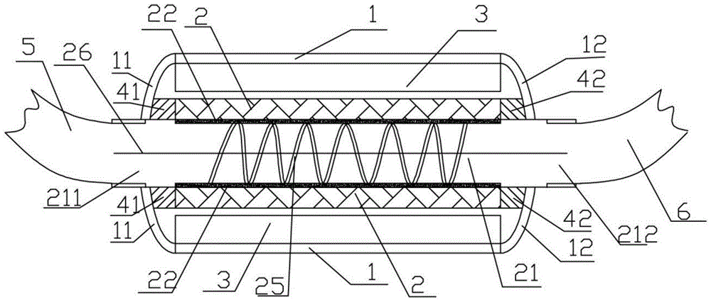
[0034] Such as figure 1 As shown, a compound generator in this embodiment includes a generator body, and the generator body includes:

[0035] Shell 1, such as figure 1 As shown, the casing 1 is a bottomless cylindrical structure, and the two ends of the casing 1 of the cylindrical structure are also provided with a first end cap 11 and a second end cap 12, the first end cap 11 and the second end cap 12 are The annular plates with the same structure, the first end cover 11 and the second end cover 12 are parallel to each other and cover the two ends of the opening of the shell 1 .

[0036] Bearing set 4, such as figure 1 As shown, the bearing set 4 includes a first bearing 41 and a second bearing 42 with the same structure, and the first bearing 41 and the second bearing 42 are symmetrically arranged on the inner walls of the two open ends of the housing 1 .

[0037] Rotor 2, such as figure 1 As shown, the rotor 2 is socketed in the casing 1 of the cylindrical structure, s...

Embodiment 2

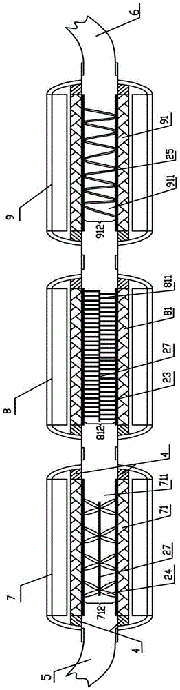
[0044] The compound generator of this embodiment includes multiple generator bodies, and the multiple generator bodies all adopt the structure of the generator body in Embodiment 1. A plurality of generator bodies in this embodiment are sequentially connected between the intake pipe 5 and the outlet pipe 6 of water or water vapor, and the passages 21 of the rotor 2 in each generator body communicate with each other; from the inlet pipe 5 to the outlet pipe 6 direction, The guide area of ​​the guide part on the rotor 2 in each generator body decreases successively.

[0045] Specific as figure 2 As shown, the composite generator formed by the combination of multiple generator bodies in this embodiment includes three generator bodies, which are respectively the first generator body 7, the second generator body 8 and the third generator body 9 , the first generator body 7 includes a first rotor 71, and the first rotor 71 includes a first channel 711 and a first guide portion 712...


PUM


Abstract

The invention relates to a combined generator which comprises a generator body. The generator body comprises a shell, a bearing set, rotors, stators, collecting rings and a terminal. The shell is of a barrel-shaped structure with openings in the two ends. The bearing set is arranged on the inner walls of the two open ends. The rotors are sleeved with the shell of the barrel-shaped structure, and the two ends of each rotor are rotatably connected with the bearing set. Hollow cylindrical channels are formed in the rotors in the direction of the center axes, and the two open ends of each channel serve as an air inlet and an air outlet of the generator body respectively. Guiding portions are arranged on the inner walls of the channels, and insulation layers are arranged on the inner walls of the channels and the guiding portions. The stators are connected to the outsides of the rotors in a sleeving mode, and the stators are not in contact with the rotors. The collecting rings are used for providing exciting current for the rotors. The terminal is connected with the stators and used for outputting current generated by power generation. The channels are formed in the direction of the center axes of the rotors, a water turbine/turbine and a generator are combined, the structure is compact, and power of water/steam is fully utilized.

Description

technical field [0001] The invention relates to a generator, in particular to a compound generator. Background technique [0002] Existing generators generally use a water turbine or a steam engine to drive the generator rotor to generate electricity, but this type of generator consumes a lot of power, and the distance between the water turbine or steam engine and the generator is relatively long, and the kinetic energy between the water turbine or steam turbine and the generator The transmission is incomplete, and the impact energy of water or steam cannot be fully utilized. Contents of the invention [0003] The technical problem to be solved by the present invention is to provide a compound generator for the deficiencies of the prior art. [0004] The technical solution of the present invention to solve the above-mentioned technical problems is as follows: a compound generator comprising a generator body, the generator body comprising: [0005] a shell, the shell is a...

Claims


Application Information

Patent Timeline
Patent Type & Authority Applications(China)
IPC IPC(8): H02K7/00H02K16/00
Inventor 刘运念
Owner 刘运念
Why Eureka
Try Eureka