Overhead line type photovoltaic power generation device and power transmission and distribution system

A photovoltaic power generation and overhead line technology, applied in photovoltaic power generation, photovoltaic power stations, photovoltaic modules, etc., can solve the problems of long installation period, high manual installation cost, and large resources, and achieve reduced civil engineering workload, reduced steel consumption, Realize the effect of economic benefit

Inactive Publication Date: 2015-12-30
付佳临 +1
View PDF10 Cites 2 Cited by
  • Summary
  • Abstract
  • Description
  • Claims
  • Application Information

AI Technical Summary

Problems solved by technology

[0002] At present, in the field of photovoltaic power generation, whether it is in a centralized power station or a distributed power station, all photovoltaic module installation systems are installed on the ground and on the roof by ground fixed brackets. The above-mentioned installation mainly has the following problems in use Problem: (1) The existing photovoltaic modules of the same specification occupy a large area, with an average area of ​​about 33-35 mu per 1MW, which occupies a huge amount of resources for the increasingly tight land resources
(2) The amount of civil construction is large, and the existing installation method is used. In the implementation, only the production of the cement foundation base consumes a lot of manpower, material and financial resources. Specifically, every 1MW needs to lay the foundation on average There are 1,440 piles, greatly increasing the investment in manpower and material resources
(4) The cost of manual installation is huge. Usually, 1MW requires at least 50 manual installations. The production and installation period is about 2 and a half months, and the installation period is long
(5) When the installation of photovoltaic modules is completed, the amount of various cables is huge, with an average laying length of about 12,000-16,000 meters per 1 MW. At the same time, the consumption of various auxiliary materials corresponding to it also increases, which intensifies the overall cost. put in
(6) Due to the long laying lines in the prior art, the power transmission will inevitably lead to an increase in loss
(7) Since the existing photovoltaic modules are installed on the ground and on the roof, and the photovoltaic modules are all fixed installations, the angle of the illumination surface cannot be adjusted according to actual needs, resulting in a decrease in efficiency

Method used


Image

  • Overhead line type photovoltaic power generation device and power transmission and distribution system
  • Overhead line type photovoltaic power generation device and power transmission and distribution system
  • Overhead line type photovoltaic power generation device and power transmission and distribution system

Examples


Embodiment 1

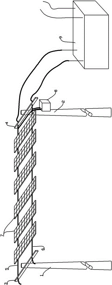
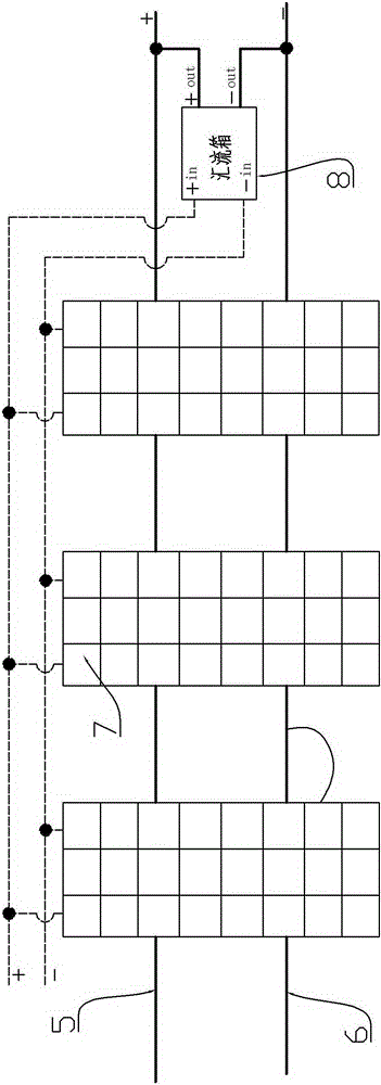
[0044] Embodiment 1: An overhead line type photovoltaic power generation device, see Figure 1 to Figure 5 ; This device includes at least one power generation unit, each power generation unit includes two fixed support parts 1, 2 (the support parts can be utility poles or iron towers or other parts), at least one group of power generation layers, wherein each layer generates electricity It includes at least one photovoltaic module 7, at least two tensile ropes 5, 6 erected in the middle of two supporting parts; the photovoltaic module 7 is arranged on the tensile rope between the two supporting parts, so as to The above-mentioned photovoltaic module 7 is installed overhead, and the light-facing surface of the photovoltaic module 7 is arranged horizontally or inclined.

[0045] For ease of understanding, this embodiment takes one power generation unit as an example for illustration; specifically, the power generation layers in this embodiment are a group, such as figure 1 As ...

Embodiment 2

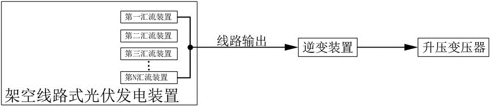
[0047] Embodiment 2: The same as Embodiment 1 will not be repeated, the difference is: there are multiple power generation units, and the multiple power generation units are connected in series or in parallel via the tension ropes in each power generation unit to form a power generation unit. Unit group; Of course, in order to ensure the safety and stability of this device, each power generation unit should also be equipped with corresponding lightning protection devices, overvoltage protection, overcurrent protection, and related protection devices for maintaining obvious disconnection points, etc. Electrical detection and protection equipment, data acquisition, communication,.

Embodiment 3

[0048] Embodiment 3: see Figure 6 ; The same as Embodiment 2 will not be repeated, the difference is: the power generation layers are two or more groups; and the multiple groups of power generation layers are arranged between two support members from top to bottom.


PUM


Abstract

The invention provides an overhead line type photovoltaic power generation device and a power transmission and distribution system, and the overhead line type photovoltaic power generation device is small in space occupation, convenient to install, low in manpower and material resource input, high in power generation efficiency and suitable for popularization. The overhead line type photovoltaic power generation device comprises at least one power generation unit. Each power generation unit comprises two fixed supporting parts and at least one group of power generation layer. Each power generation layer comprises at least one photovoltaic component, and at least two anti-tension ropes which are erected between the two supporting parts. The photovoltaic components are arranged on the anti-tension ropes arranged between the two supporting parts so that the photovoltaic components are enabled to be arranged in an overhead way, and the light receiving surfaces of the photovoltaic components face upwardly and are arranged in a horizontal or inclined way. The power transmission and distribution system comprises the overhead line type photovoltaic power generation device, and also comprises an inversion device and a step-up transformer which is correspondingly connected with the inversion device. The current output ends of the power generation units or the power generation unit groups are electrically connected with the inversion device correspondingly.

Description

technical field [0001] The invention relates to the technical field of photovoltaic power generation and power transmission and distribution, in particular to an overhead line photovoltaic power generation device and power transmission and distribution system. Background technique [0002] At present, in the field of photovoltaic power generation, whether it is in a centralized power station or a distributed power station, all photovoltaic module installation systems are installed on the ground and on the roof by ground fixed brackets. The above-mentioned installation mainly has the following problems in use Problems: (1) The existing photovoltaic modules of the same specification occupy a large area, with an average area of ​​about 33-35 mu per 1MW, which occupies a huge amount of resources for the increasingly tense land resources. (2) The amount of civil construction is large, and the existing installation method is used. In the implementation, only the production of the ...

Claims


Application Information

Patent Timeline
Patent Type & Authority Applications(China)
IPC IPC(8): H02S10/00H02S40/34H02S20/30
CPCY02E10/50
Inventor 付佳临邹胜萍
Owner 付佳临
Why Eureka
Try Eureka