Supercharge Your Innovation With Domain-Expert AI Agents!

Air jet weaving machine comprising electromagnetic valve

A knitting machine and valve technology, which is applied in the field of knitting machines, can solve the problems of expensive compressed air, etc., and achieve the effects of short response time, reduced losses, and cost savings

Inactive Publication Date: 2015-12-30
范德威尔(中国)纺织机械有限公司
View PDF6 Cites 1 Cited by
  • Summary
  • Abstract
  • Description
  • Claims
  • Application Information

AI Technical Summary

Problems solved by technology

Compressed air is expensive in terms of the electrical energy required to power an air compression unit

Method used


Image

  • Air jet weaving machine comprising electromagnetic valve
  • Air jet weaving machine comprising electromagnetic valve
  • Air jet weaving machine comprising electromagnetic valve

Examples


Embodiment Construction

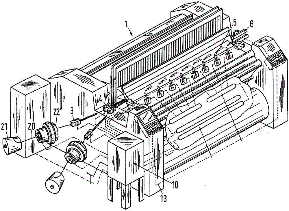
[0026] figure 1 A conventional air-jet knitting machine 1 is shown in . Air jet knitting machines may generally include weft yarn 20 disposed on one or more yarn bobbins 21 . exist figure 1 In the air-jet knitting machine, the weft yarn 20 enters the weft yarn storage device / feeder 22. The weft yarn is picked from the pre-feeder 22 through the main nozzle 4 . The main nozzle 4 can be preceded by one or more pre-nozzles 3 . There can be several pre-nozzles and main nozzles 4 . The nozzles 3 and 4 are supplied with compressed air from the air supply unit 10 through the line 13 . Furthermore, in order to convey the weft thread 20 completely through the shed of the air-jet weaving machine, a relay nozzle 5 may be provided. The relay nozzle is also supplied with compressed air from the compressed air supply unit 10 . Furthermore, one or more stretching nozzles 6 may be provided to ensure that the weft yarn remains stretched until the shed is closed after the weft yarn reache...


PUM

PropertyMeasurementUnit
Thicknessaaaaaaaaaa
Diameteraaaaaaaaaa

Abstract

Described are, among other things, an air-jet weaving machine (1) comprising a compressed air valve and nozzle arrangement (31, 35) with improved response time, and which may also have a lower variance in its response time. Hereby a more efficient use of energy can be achieved in the air-jet weaving machine. The valve and nozzle arrangement (31, 35) is connected to a compressed air supply feeding the nozzle(s) via the valve(s) with the compressed air. The valve is an electromagnetic valve having a core that can be magnetized using a coil fed with an excitation current. The valve further comprises a valve member (49). The valve member can in particular be formed by a number of flexible plates (51, 91) stacked on top of each other. The plates are, at least partly, made of a magnetisable material. The valve member is located in a space interconnecting an inlet and outlet of the valve. The valve member can move in the space between two positions; a first position when there is no excitation current in the coil, and a second position when there is an excitation current in the coil. In one of the two positions the valve member is forced to close, in the other position to open a compressed air flow channel formed in the space between the inlet and outlet of the valve and leading further to the nozzle (35).

Description

technical field [0001] The present disclosure relates to a knitting machine. Specifically, the present disclosure relates to an air jet knitting machine. Background technique [0002] A variety of braiding machines currently exist. One such knitting machine is a so-called air-jet knitting machine. In an air-jet knitting machine, a jet of air is used to insert the weft yarn. The air jet is formed by opening and closing a valve / valves to allow a stream of compressed air to pass through the nozzle. Air is blown to the weft yarn through nozzles, thereby transporting the weft yarn from one end of the shed (insertion end) to the other end of the shed (arrival end). To ensure that the weft yarn reaches the arrival end of the shed completely, a relatively large number of air jet nozzles are usually provided. Firstly, in order to start and accelerate the weft thread at the correct time, one or more main nozzles are provided. Secondly, in order to maintain the flight and the spe...

Claims


Application Information

Patent Timeline
IPC IPC(8): D03D47/30
CPCD03D47/306F16K31/0658
Inventor P·约瑟夫松T·伦德贝里P-O·约翰松
Owner 范德威尔(中国)纺织机械有限公司
Features
  • R&D
  • Intellectual Property
  • Life Sciences
  • Materials
  • Tech Scout
  • Unparalleled Data Quality
  • Higher Quality Content
  • 60% Fewer Hallucinations
Learn More