Power transmission device, power transmission and receiving device, method for detecting power receiving device, power receiving device detection program, and semiconductor device

A technology of power receiving device and power transmission device, applied in circuit devices, battery circuit devices, transportation and packaging, etc., can solve problems such as increased power consumption, and achieve the effect of easy detection, short time and detection

Inactive Publication Date: 2015-12-30
DEXERIALS CORP
View PDF7 Cites 7 Cited by
  • Summary
  • Abstract
  • Description
  • Claims
  • Application Information

AI Technical Summary

Problems solved by technology

[0005] When polling is performed frequently like this, the power consumption of mobile phones and smartphones that operate on batteries increases, so it is desirable to perform detection of devices and equipment on the secondary side with as little power consumption as possible. request stronger

Method used


Image

  • Power transmission device, power transmission and receiving device, method for detecting power receiving device, power receiving device detection program, and semiconductor device
  • Power transmission device, power transmission and receiving device, method for detecting power receiving device, power receiving device detection program, and semiconductor device
  • Power transmission device, power transmission and receiving device, method for detecting power receiving device, power receiving device detection program, and semiconductor device

Examples


Embodiment Construction

[0040] Below, while referring to the attached Figure 1 Modes for implementing the present invention will be described in detail. In addition, this invention is not limited only to the following embodiment, It goes without saying that various changes can be made in the range which does not deviate from the summary of this invention. In addition, description will be given in the following order.

[0041] 1. Structural example of power transmission device

[0042] 2. Principle and work of power transmission device

[0043] 2-1. Differences in the frequency characteristics of the antenna current in the case of the power receiving device and foreign objects

[0044] 2-2. Detection of difference in frequency characteristics of antenna current at weak coupling

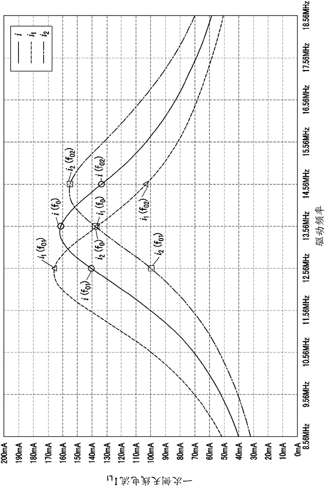
[0045] 2-3. Resonant frequency deviation on the receiving device side

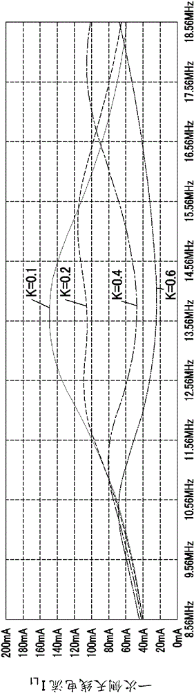
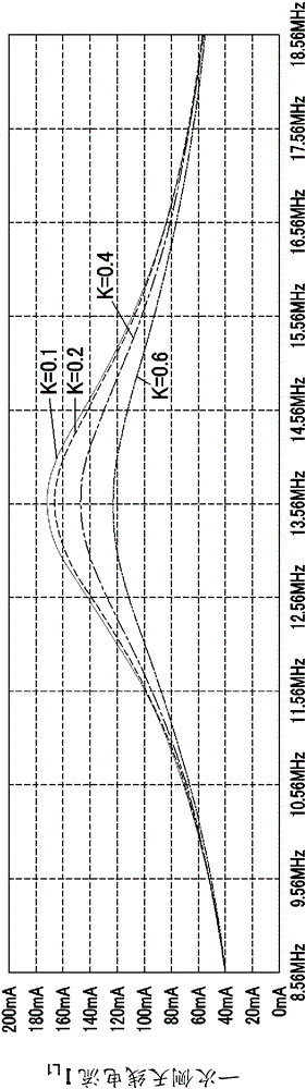
[0046] 2-4. Detection of difference in frequency characteristics of antenna current when coupling coefficient changes

[0047] 2-5. Detection mode...


PUM


Abstract

The purpose of the present invention is to provide a power transmission device capable of highly accurate discrimination between a device placed on a secondary side and a foreign object without additional complex circuitry. The power transmission device comprises: a control unit (5a) for setting the drive frequency of a signal which drives a resonant circuit; an inverter unit (2) for driving the resonant circuit at three or more drive frequencies on the basis of the settings of the control unit (5a); and a waveform monitoring unit (4) for detecting the drive waveform of the resonant circuit. The control unit (5a), in accordance with the procedures of a program stored in a storage unit (5b), sets the three or more drive frequencies, compares signal data in each drive frequency detected by a drive waveform detection unit, and detects a power receiving device (50) on the basis of the comparison results.

Description

technical field [0001] The present invention relates to a power transmission device for transmitting or receiving power from a non-contact communication device, a power transmission and reception device, a power reception device detection method, a power reception device detection program, and a semiconductor device. This application claims priority on the basis of Japanese Patent Application No. Japanese Patent Application No. 2013-60646 for which it applied in Japan on March 22, 2013, and uses this application by referring to this application. Background technique [0002] A non-contact communication technology utilizing electromagnetic induction is frequently applied to IC cards such as FeliCa (registered trademark), Mifare (registered trademark), and NFC (Near Field Communication). In recent years, it is also applied to non-contact charging (power supply) technology represented by the Qi format (format), showing expansion. In the field of non-contact charging technology...

Claims


Application Information

Patent Timeline
Patent Type & Authority Applications(China)
IPC IPC(8): H02J17/00H02J7/00
CPCH02J50/12H02J50/80H02J50/60H02J50/90
Inventor 管野正喜
Owner DEXERIALS CORP
Why Eureka
Try Eureka