
Automatic gas blowing device for eliminating residual engine oil in engine

An air blowing device and engine technology, applied in cleaning methods and utensils, cleaning methods using gas flow, chemical instruments and methods, etc., can solve the problems of oil waste, residual oil, complicated oil passages in the engine cavity, etc. Production cost, pollution prevention effect

Inactive Publication Date: 2016-01-06
GUANGXI YUCHAI MASCH CO LTD
View PDF13 Cites 5 Cited by
  • Summary
  • Abstract
  • Description
  • Claims
  • Application Information

AI Technical Summary

Problems solved by technology

[0002] During the production process of the engine, engine oil must be added for performance adjustment, but in order to reduce manufacturing costs, the engine oil used for engine performance adjustment is recycled and filtered oil that has been reused many times, and the reused engine oil appears darker than new engine oil
Before the engine leaves the factory, the oil used for performance debugging needs to be released. However, due to factors such as the viscosity of the engine oil, the complexity of the oil passage in the engine cavity, the different assembly positions of the oil drain plug, and the engine hanging by the suspension chain is not in a horizontal position. It is impossible to completely drain the engine oil in the engine cavity, and a certain amount of engine oil will remain in the engine and be taken out of the factory
[0003] Nowadays, the natural discharge method is generally used, but the residual oil in the engine body cannot be drained cleanly. If there is too much residual oil in the engine belt, it will not only cause waste of oil and increase manufacturing costs, but also cause problems with the new oil added by the car factory. Mixed use will make the new engine oil black and affect the quality of the new engine oil

Method used


Image

  • Automatic gas blowing device for eliminating residual engine oil in engine
  • Automatic gas blowing device for eliminating residual engine oil in engine

Examples


Embodiment Construction

[0014] The specific embodiments of the present invention will be described in detail below in conjunction with the accompanying drawings, but it should be understood that the protection scope of the present invention is not limited by the specific embodiments.

[0015] Unless expressly stated otherwise, throughout the specification and claims, the term "comprise" or variations thereof such as "includes" or "includes" and the like will be understood to include the stated elements or constituents, and not Other elements or other components are not excluded.

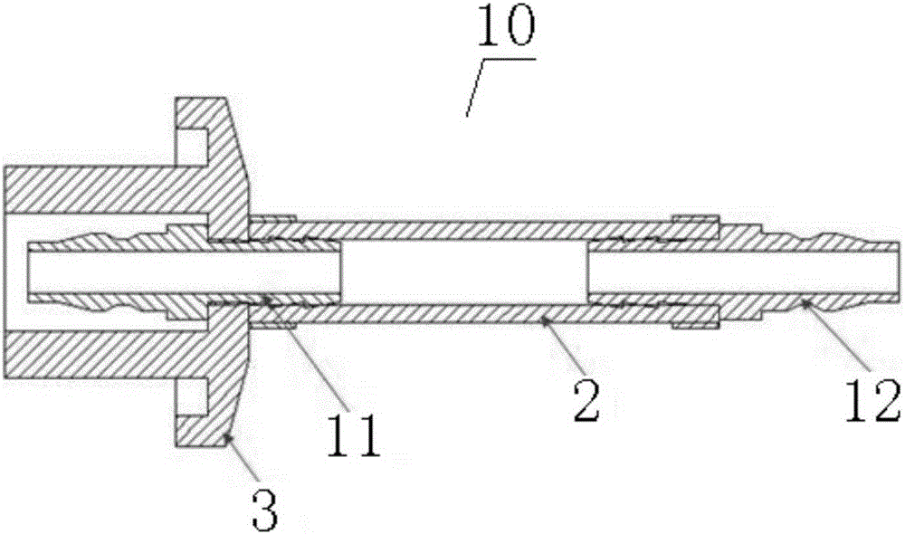
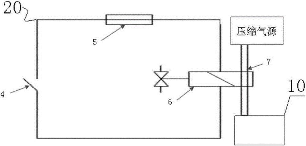
[0016] Such as Figure 1 to Figure 2 As shown, according to a specific embodiment of the present invention, an automatic air blowing device for removing residual oil in the engine, the engine has an oil filling port, and the oil filling port is provided with an oil port cover, and the automatic air blowing device includes a compressed air source, The connector 10 and the controller 20. Wherein the connector 10 comprises a...


PUM


Abstract

The invention discloses an automatic gas blowing device for eliminating residual engine oil in an engine. The engine comprises an engine oil adding opening which is provided with an engine oil opening cover. The automatic gas blowing device comprises a compressed gas source, a connector and a controller. The connector comprises a cover-shaped piece used for being arranged on the engine oil adding opening in a covering manner;a first connector penetrates the end face of the cover-shaped piece, and a second connector is connected with the first connector through a gas pipe. The second connector is used for being communicated with the compressed gas source. The controller comprises a timekeeper and an electromagnetic valve. The electromagnetic valve is used for controlling the second connector to be connected or disconnected with the compressed gas source. The timekeeper controls the opening and closing time of the electromagnetic valve. By means of the automatic gas blowing device, the production cost of an engine factory can be reduced, the potential hazard that an automobile factory is stained by residual engine oil when new engine oil is added can be prevented, and the quality of the new engine oil can be ensured.

Description

technical field [0001] The invention relates to the technical field, in particular to an automatic air blowing device for removing residual engine oil inside an engine. Background technique [0002] During the production process of the engine, engine oil must be added for performance adjustment. However, in order to reduce the manufacturing cost, the engine oil used for engine performance adjustment is recycled and filtered oil that has been reused many times. The reused engine oil appears darker than new engine oil. Before the engine leaves the factory, the oil used for performance debugging needs to be released. However, due to factors such as the viscosity of the engine oil, the complexity of the oil passage in the engine cavity, the different assembly positions of the oil drain plug, and the engine hanging by the suspension chain is not in a horizontal position. It is impossible to completely drain the engine oil in the engine cavity, and a certain amount of engine oil w...

Claims


Application Information

Patent Timeline
IPC IPC(8): B08B5/02
CPCB08B5/02
Inventor 吴锦权黄祖胜邱亚勇徐春林李家钊
Owner GUANGXI YUCHAI MASCH CO LTD
Learn More