Rapid mounting tool rest for turning tool

A technology of turning tools and tool holders, which is applied in the direction of tool holders, etc., can solve the problems of different workpiece quality, high labor intensity, and low tool loading efficiency, and achieve the effects of prolonging tool life, reducing labor intensity, and improving tool loading efficiency

Inactive Publication Date: 2016-01-06
FLIGHT AUTOMATIC CONTROL RES INST
View PDF9 Cites 3 Cited by
  • Summary
  • Abstract
  • Description
  • Claims
  • Application Information

AI Technical Summary

Problems solved by technology

On the mirror surface of a laser gyro cathode (the surface roughness Ra value is required to be 0.1 microns), a highly skilled operator uses the above manual method to install the turning tool, and repeatedly tries cutting, adjusting the tool shim, and retrying cutting, which takes 20 hours. F

Method used


Image

  • Rapid mounting tool rest for turning tool
  • Rapid mounting tool rest for turning tool
  • Rapid mounting tool rest for turning tool

Examples


Example Embodiment

[0012] Example:

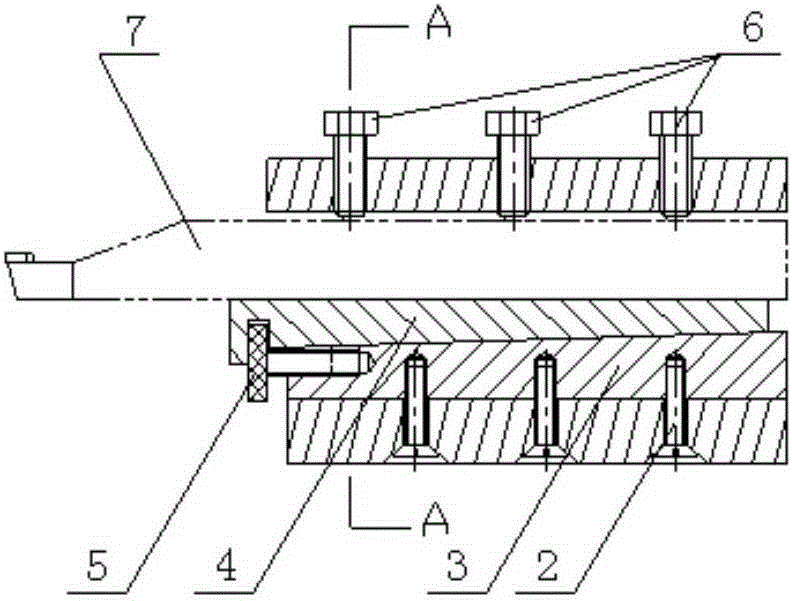
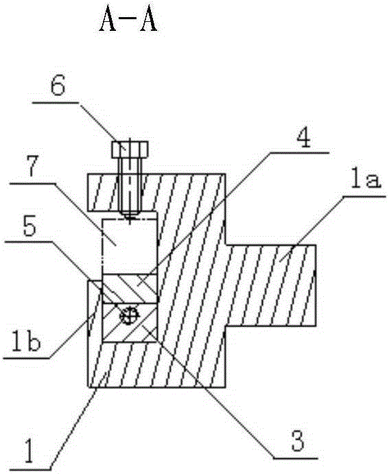
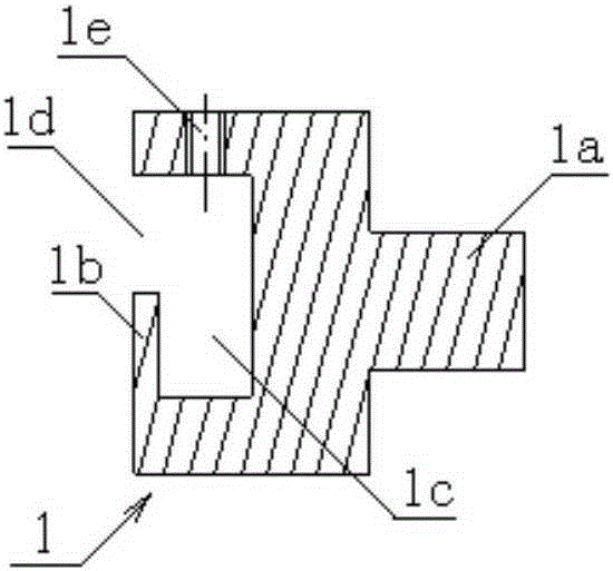
[0013] On the upper surface of the tool holder mounting seat, there are three threaded holes 1e on the body, which are distributed along the length of the body 1 and penetrate vertically through the top surface of the turning tool mounting groove 1c. In each threaded hole 1e on the body, a pressing Bolt 6, on the lower surface of the tool holder mounting seat, there are three countersunk head body lower threaded holes distributed along the length direction of the body 1 and vertically penetrating the bottom surface of the turning tool mounting groove 1c. The angle value of the wedge structure of the static inclined iron 3 is 6°.

[0014] Using the above example to process the cathode inner hole of a Zeeman laser gyro product, the surface roughness Ra value is required to be 0.1 microns. In the mirror lathe, the original highly skilled operator installed the turning tool manually, and repeated trial cutting. , Adjust the shim, and try cutting again, which tak...


PUM


Abstract

The invention belongs to the turning technology, and relates to a rapid mounting tool rest for a turning tool for turning. The rapid mounting tool rest is characterized by being composed of a body (1), sunk screws (2), a static inclined iron (3), a movable inclined iron (4), an adjusting screw (5) and pressing bolts (6). According to the rapid mounting tool rest for the turning tool, the rapid mounting of the turning tool is achieved, the tool mounting efficiency is improved, the labor intensity is lowered, and the machining quality is guaranteed.

Description

technical field [0001] The invention belongs to the turning technology, and relates to a quick-install tool holder for turning tools. Background technique [0002] The installation of the turning tool in turning is mainly the process of adjusting the tool tip to coincide with the center of rotation of the machine tool spindle in the vertical direction (Z direction) and maintaining its correct position. At present, in production practice, the installation of the turning tool is mainly completed by the operator relying on experience to visually observe the position of the tool tip, try to cut a sample, and manually adjust the tool shim. When the turning tool is installed, the position of the tool tip is too high or too low relative to the center of rotation of the machine tool spindle, which will cause the actual working angle of the turning tool to change relative to its ideal geometric angle during the turning process, which will affect the turning quality and reduce the tur...

Claims


Application Information

Patent Timeline
IPC IPC(8): B23B29/06
CPCB23B29/06
Inventor 李鹏立徐长洲
Owner FLIGHT AUTOMATIC CONTROL RES INST
Why Eureka
Try Eureka