Steel bar punching and blanking machine with automatic feeding function

An automatic feeding and steel bar technology, applied in the direction of shearing devices, manufacturing tools, shearing machine accessories, etc., can solve the problems of low production efficiency, poor operation convenience, complex structure, etc., and achieve high production efficiency and punching operation Simple and convenient, simple structure effect

Inactive Publication Date: 2016-01-06
CHONGQING CHANGZHAN MACHINERY
View PDF7 Cites 12 Cited by
  • Summary
  • Abstract
  • Description
  • Claims
  • Application Information

AI Technical Summary

Problems solved by technology

[0003] In view of this, the object of the present invention is to provide a steel bar punching and blanking machine with automatic feeding function to solve the problems of complex structure, poor operation convenience and low production efficiency of the steel bar blanking device in the prior art

Method used


Image

  • Steel bar punching and blanking machine with automatic feeding function
  • Steel bar punching and blanking machine with automatic feeding function

Examples


Embodiment Construction

[0013] The present invention will be further described below in conjunction with the accompanying drawings and embodiments.

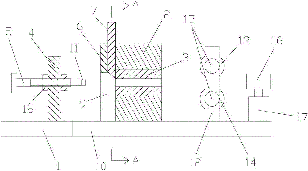
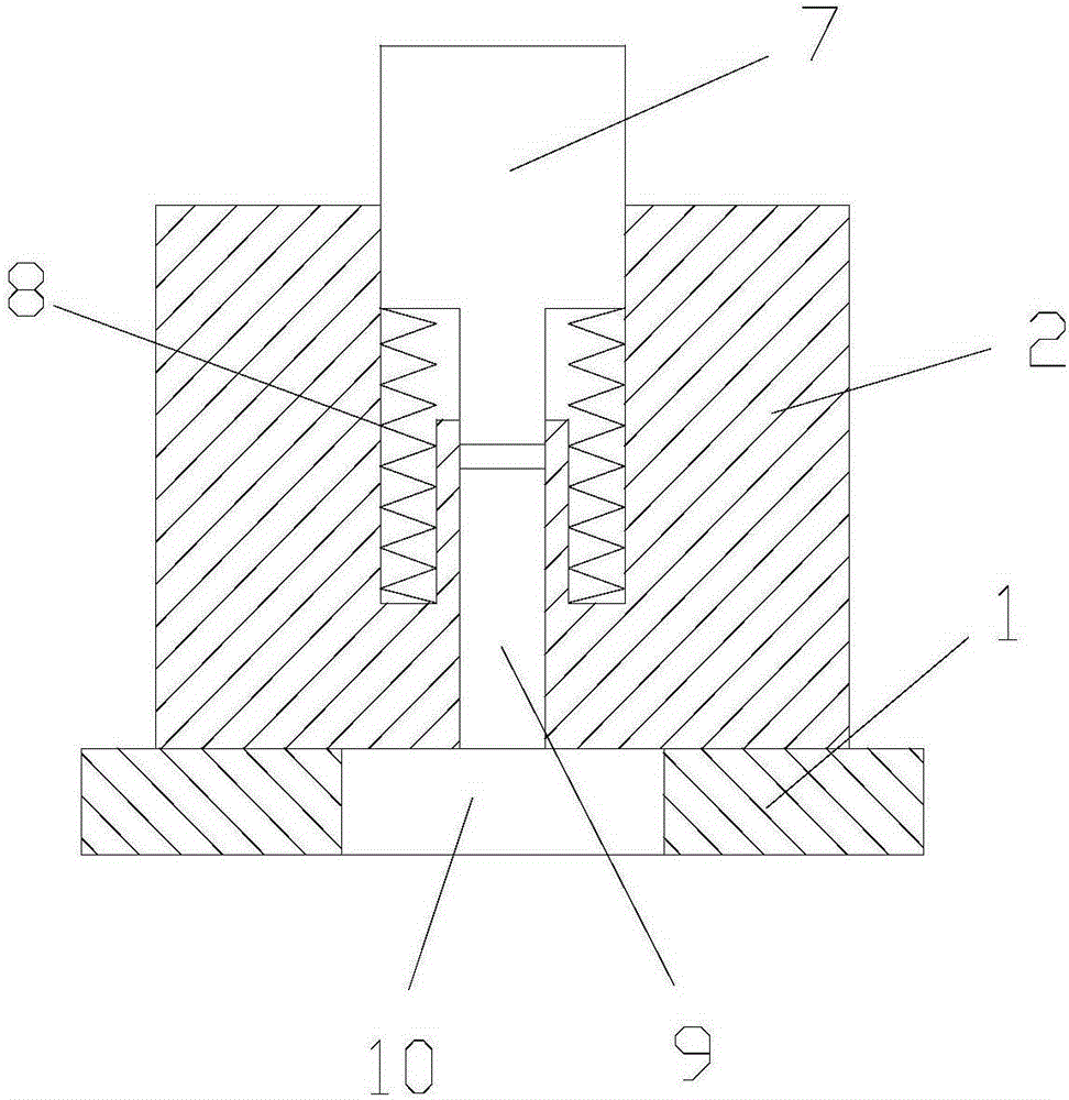
[0014] As shown in the figure, the steel bar punching and blanking machine with automatic feeding function in this embodiment includes a base 1, a positioning device, a cutter device and a feeding device. The positioning sleeve 3 arranged in the first vertical plate, the second vertical plate 4 fixed on the base, and the ejector rod 5 arranged on the second vertical plate, the ejector rod and the positioning sleeve are coaxial;

[0015] The cutter device includes a knife seat 6 fixed on the first vertical plate, a cutter 7 that slides up and down with the knife seat, and a return spring 8 that is arranged on the knife seat and pushes the cutter upwards. Sliding up and down with the end face of the positioning sleeve;

[0016] The knife seat is provided with a blanking groove 9 directly below the cutting edge, and a blanking hole 10 is provided on the b...


PUM


Abstract

The invention discloses a steel bar punching and blanking machine with the automatic feeding function. The steel bar punching and blanking machine comprises a base, a locating device, a cutter device and a feeding device. The cutter device comprises a cutter holder and a return spring. The feeding device comprises a pressure sensor, vertical clamping rollers and horizontal clamping rollers. In work, a steel bar manually penetrates a locating hole of a locating sleeve through the vertical clamping rollers and the horizontal clamping rollers, and the steel bar is pushed by the feeding device to move forwards; after the front end of the steel bar abuts against the pressure sensor, a controller controls a press head of a hydraulic machine to move downwards to push a cutter to move downwards, and the steel bar is then punched at the stipulated length; and after the steel bar is punched, the cutter returns to the original position upwards under the effect of the return spring, and meanwhile short-section materials generated after punching operation fall into a collecting device through a discharging groove and a discharging hole. The steel bar punching and blanking machine with the automatic feeding function is simple in structure, punching operation is easy and convenient, the automatic feeding function is achieved, and production efficiency is high.

Description

technical field [0001] The invention relates to a mechanical device, in particular to a steel bar cutting machine. Background technique [0002] The short section steel bar section is the raw material for producing screws, rivets, pins and other parts, and the short section steel bar section is obtained by punching the long steel bar through the blanking machine. There are many punching devices in the prior art, but all of them have the problems of complex structure, poor operation convenience and low production efficiency. Contents of the invention [0003] In view of this, the object of the present invention is to provide a steel bar punching and blanking machine with automatic feeding function to solve the problems of complex structure, poor operation convenience and low production efficiency of the steel bar blanking device in the prior art. [0004] The steel bar punching and blanking machine with automatic feeding function of the present invention includes a base, a...

Claims


Application Information

Patent Timeline
Patent Type & Authority Applications(China)
IPC IPC(8): B23D27/00B23D33/02
Inventor 樊绍洪
Owner CHONGQING CHANGZHAN MACHINERY
Why Eureka
Try Eureka