
Cloth cutting device capable of replacing blade for textile fabric processing

A technology of textile fabrics and blades, applied in the field of fabrics, can solve the problems of cumbersome disassembly, movement of fabrics, inconvenient use, etc., and achieve the effects of high feeding accuracy, easy replacement, and prevention of movement.

Active Publication Date: 2021-05-28
苏州帛乐纺织有限公司
View PDF5 Cites 3 Cited by
  • Summary
  • Abstract
  • Description
  • Claims
  • Application Information

AI Technical Summary

Problems solved by technology

[0004] The purpose of the present invention is to solve the problems in the prior art that the cloth cutting machine in the prior art needs to be cumbersomely disassembled when replacing the cutting blade, so that it is not convenient to replace the blade, and when cutting, the fabric will move, which will cause The cutting part of the fabric is not neat enough, so the cutting effect is not good, and there is no automatic feeding function. It is necessary to manually place the fabric under the blade, so that the cutting length needs to be controlled manually, which is not easy to use. Cloth cutting device for textile fabric processing with blade replacement

Method used


Image

  • Cloth cutting device capable of replacing blade for textile fabric processing
  • Cloth cutting device capable of replacing blade for textile fabric processing
  • Cloth cutting device capable of replacing blade for textile fabric processing

Examples


Embodiment Construction

[0025] The following will clearly and completely describe the technical solutions in the embodiments of the present invention with reference to the accompanying drawings in the embodiments of the present invention. Obviously, the described embodiments are only some, not all, embodiments of the present invention.

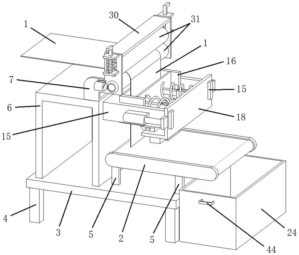
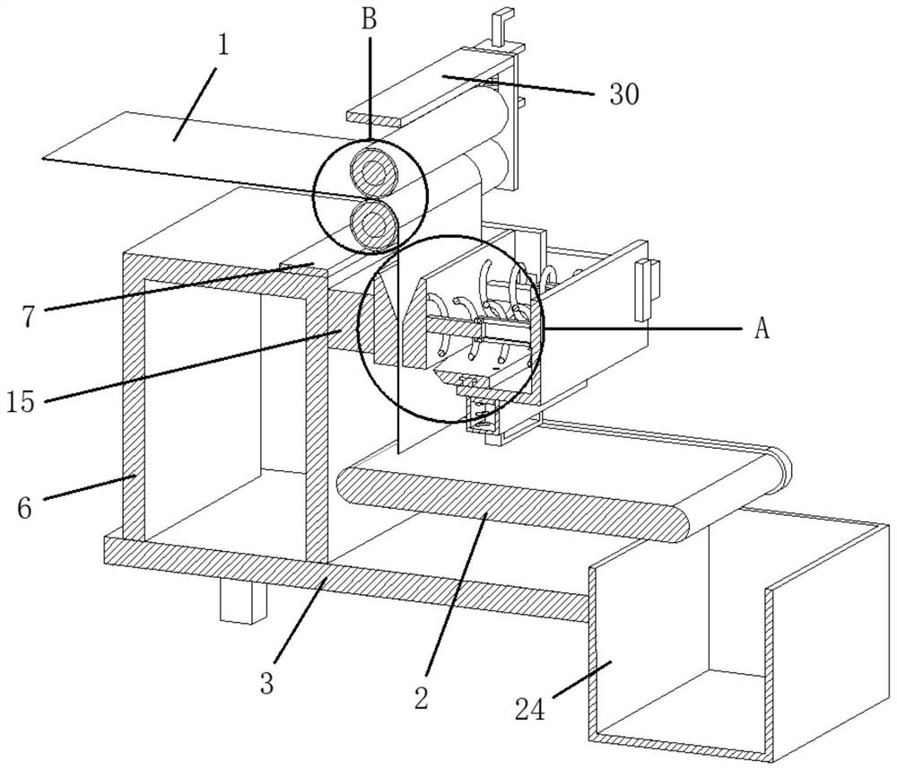
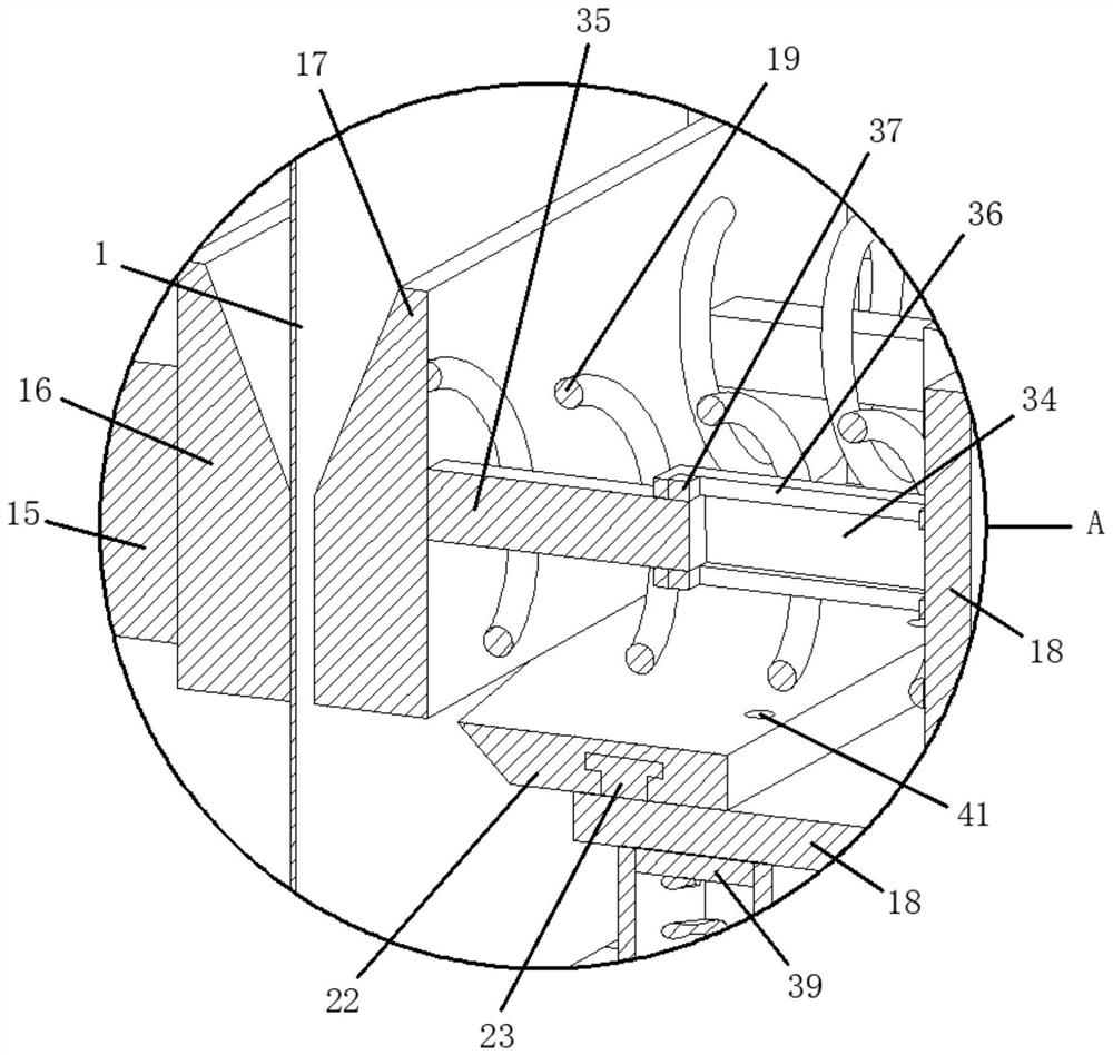
[0026] refer to Figure 1-8, a cloth cutting device for textile fabric processing that can replace blades, comprising a fabric 1, a conveyor belt 2, a worktable 3 is provided on one side of the fabric 1, a plurality of support legs 4 are fixedly provided on one side of the workbench 3, and the conveyor belt 2 One side is fixed with a number of support rods 5, the other ends of the support rods 5 are fixedly connected to one side of the worktable 3, one side of the worktable 3 is fixed with an inverted U-shaped frame 6, and one side of the inverted U-shaped frame 6 A Z-shaped hollow frame 7 is fixedly arranged, and one side of the Z-shaped hollow frame 7 is provided w...


PUM


Abstract

The invention relates to the technical field of fabric, in particular to a cloth cutting device capable of replacing a blade for textile fabric processing. The cloth cutting device comprises the fabric and a conveyor belt, wherein a working table plate is arranged on one side of the fabric, a plurality of supporting legs are fixedly arranged on one side of the working table plate, a plurality of supporting rods are fixedly arranged on one side of the conveyor belt, the other end of each supporting rod is fixedly connected to one side of the working table plate, an inverted-U-shaped frame is fixedly arranged on one side of the working table plate, a Z-shaped hollow frame is fixedly arranged on one side of the inverted-U-shaped frame, and a driving shaft is arranged on one side of the Z-shaped hollow frame. Through arrangement of the driving shaft, a servo motor, a driving discharging barrel, a pressing shaft, a movable hole, a driven pressing barrel, a U-shaped clamping base, a sliding clamping base, an L-shaped sliding frame, a spring, a telescopic hydraulic cylinder, a bevel edge cutter and a T-shaped fixing strip, the automatic cutting device has the functions of automatic feeding, accurate feeding, automatic cutting, deviation prevention, convenience in blade replacement, automatic collection and the like.

Description

technical field [0001] The invention relates to the technical field of fabrics, in particular to a cloth cutting device for textile fabric processing that can replace blades. Background technique [0002] Fabric is the material used to make clothing. As one of the three elements of clothing, fabric can not only interpret the style and characteristics of clothing, but also directly affect the color and shape of clothing. Strips of fabric are cut into lengths of fabric. [0003] Cloth cutting machines in the prior art need to be cumbersomely disassembled when replacing the cutting blades, so that it is not convenient to replace the blades, and when cutting, the fabric will move, which will cause the cutting of the fabric to be not neat enough, so that the cutting effect is not good. It is good, and there is no automatic feeding function. It is necessary to manually place the cloth under the blade, so that the cutting length needs to be controlled manually, which is not easy t...

Claims


Application Information

Patent Timeline
Patent Type & Authority Applications(China)
IPC IPC(8): D06H7/00
CPCD06H7/00
Inventor 沈菊
Owner 苏州帛乐纺织有限公司
Learn More