Spiral steering clamp for numerical control machine tool

A CNC machine tool and screw technology, applied in the direction of clamping, clamping device, manufacturing tool, etc., can solve the problems of vibration, easy deformation, inaccurate positioning, etc.

Inactive Publication Date: 2016-01-06
NINGBO LONGYUAN PRECISION MACHINERY
View PDF0 Cites 2 Cited by
  • Summary
  • Abstract
  • Description
  • Claims
  • Application Information

AI Technical Summary

Problems solved by technology

[0002] At present, most of the fixtures of CNC machine tools are prone to deformation after clamping thin-walled and deformable precision parts, and the parts often have displacement, vib...

Method used


Image

  • Spiral steering clamp for numerical control machine tool
  • Spiral steering clamp for numerical control machine tool
  • Spiral steering clamp for numerical control machine tool

Examples


Embodiment

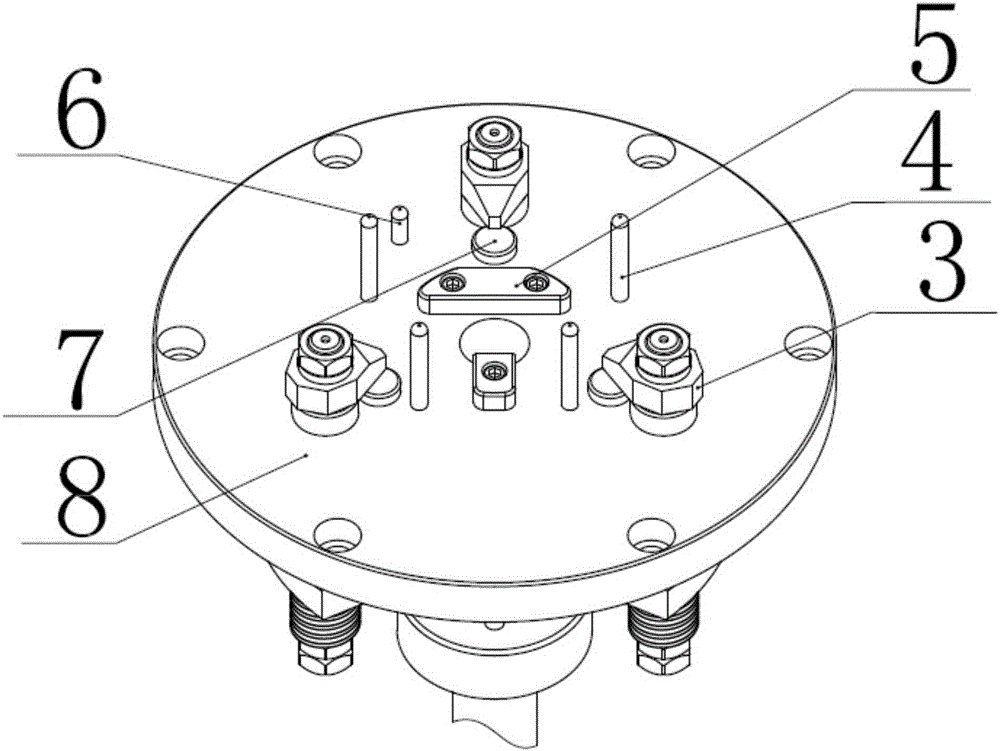
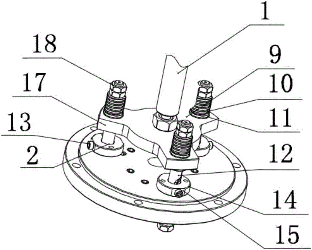
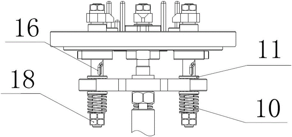
[0024] When the product is processed, the product is first positioned, and the product is placed in the positioning block 5 along the product guide pin 4 for positioning, orientated by the orientation pin 6, and the product position is adjusted until the support nail 7 stabilizes the lower end surface of the product. The brake system pulls the pull rod 1 to drive the pull plate 9 to compress the spring 10, and transmits the elastic force to the steering shaft 12 through the thrust ball bearing 11 to make it pull down, the guide screw 13 moves along the spiral guide rail 16, and the pressure plate 3 turns and turns The product is pressed tightly. After the product is processed, the hydraulic mechanical brake system of the machine tool pushes out the tie rod 1, drives the pull plate 9, and pushes up the steering shaft 12 through the thrust ball bearing 11, so that the pressure plate 3 is released, and the product is taken out. The invention has the characteristics of no displacem...


PUM


Abstract

The invention relates to a spiral steering clamp for a numerical control machine tool. The spiral steering clamp comprises a fixing plate and steering shafts. A positioning block is arranged at the position, close to the circle center, of the upper end face of the fixing plate. Multiple fixing blocks are evenly arranged at the positions, around the circle center, of the lower end face of the fixing plate. Cylindrical holes allowing the steering shafts to pass are formed in the middle portions of the fixing blocks. A pulling plate is arranged below the fixing plate in parallel. A pulling rod is vertically connected to the center of the lower end face of the pulling plate. The steering shafts vertically penetrate the pulling plate, the fixing blocks and the fixing plate from bottom to top. A pressing plate is installed at the upper ends, penetrating the fixing plate, of the steering shafts. Hexagon nuts are fixedly installed at the lower ends of the steering shafts. The portions, between the hexagon nuts and the lower end face of the pulling plate, of the steering shafts are sleeved with springs. Spiral rails are arranged on the side walls of the steering shafts. A guiding screw is horizontally installed on the side wall of one end of each fixing block. One ends of the guiding screws are embedded into the spiral rails and slide along the spiral rails along with movement of the steering shafts in the cylindrical holes. The spiral steering clamp has the beneficial effects that no displacement or tool vibration or deformation is generated in the machining process, and positioning is accurate.

Description

technical field [0001] The invention relates to the technical field of clamps, in particular to a screw steering clamp for a numerically controlled machine tool. Background technique [0002] At present, most of the fixtures of CNC machine tools are prone to deformation after clamping thin-walled and deformable precision parts, and the parts often have displacement, vibration, and inaccurate positioning during the processing process. It is also more complicated, so it is necessary to optimize the existing CNC machine tool fixture structure for these phenomena. Contents of the invention [0003] The technical problem to be solved by the present invention is to provide a numerical control machine tool screw steering fixture, which has the characteristics of no displacement, no vibration of the knife, no deformation, and accurate positioning during the processing. [0004] The technical solution adopted by the present invention to solve the technical problem is to provide a ...

Claims


Application Information

Patent Timeline
IPC IPC(8): B23Q3/00
CPCB23Q3/00B23Q2703/04B23Q2703/10
Inventor 林国栋潘建陈浩张必胜陈艳华钱淑娟蒋华君
Owner NINGBO LONGYUAN PRECISION MACHINERY
Why Eureka
Try Eureka