A multifunctional drilling and milling mechanism

A multi-functional, drilling and milling technology, applied in the direction of metal processing machinery parts, other manufacturing equipment/tools, large fixed members, etc., can solve the problem that it is difficult to ensure the position accuracy and shape accuracy of parts, increase the labor intensity of producers, and disadvantage large batches Production and other issues, to achieve the effect of high rigidity, low manufacturing cost, and stable processing dimensions

Active Publication Date: 2016-05-18
安阳市海之达新型建材有限公司
View PDF5 Cites 0 Cited by
  • Summary
  • Abstract
  • Description
  • Claims
  • Application Information

AI Technical Summary

Problems solved by technology

Since this process requires repeated clamping, it is difficult to ensure the positional accuracy and shape accuracy of the parts, and the production efficiency is low, which increases the labor intensity of the producer and is not conducive to mass production
In addition, traditional machine tools need to use at least three servo motors, which increases energy consumption and is not conducive to environmental protection

Method used


Image

  • A multifunctional drilling and milling mechanism
  • A multifunctional drilling and milling mechanism
  • A multifunctional drilling and milling mechanism

Examples


Embodiment Construction

[0022] The present invention will be further described below in conjunction with the accompanying drawings.

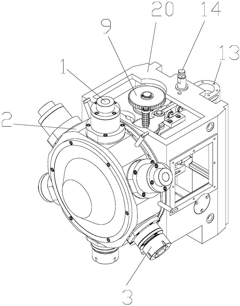
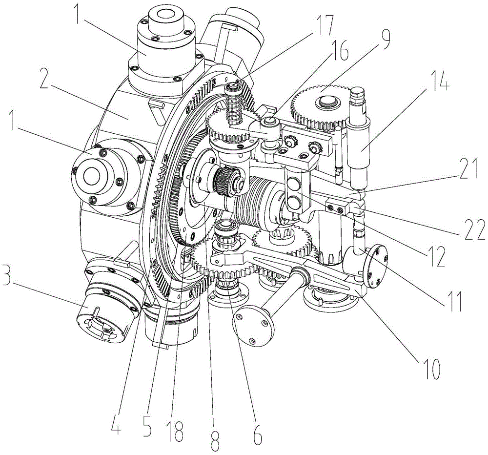
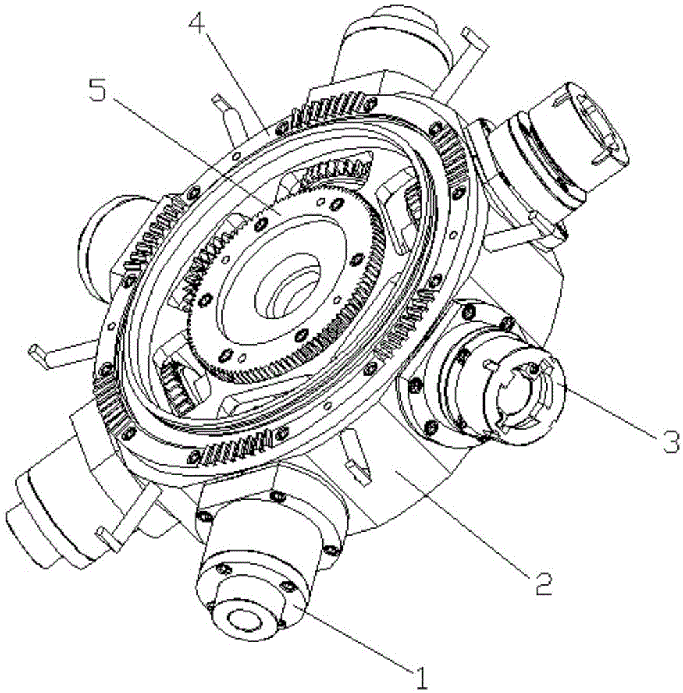
[0023] see Figure 1 to Figure 11 , a multifunctional drilling and milling mechanism of the present invention, comprising a spindle head and a headstock; the spindle head includes four drilling power heads 1, a headstock housing 2, two milling power heads 3, a Hirth 4 and a cutter head gear 5. Among them, four drilling power heads 1 and two milling power heads 3 are evenly arranged along the circumference of the cylindrical contour surface of the headstock shell 2, and are installed on the headstock shell 2 through bearing supports, and two The milling power head 3 is adjacently arranged along the cylindrical contour surface of the headstock housing 2; the hirth disc 4 is installed on the end face of the headstock housing 2 side, and the cutter head gear 5 is installed on the center of the headstock housing 2; The main shaft head is connected on one end of the main sh...


PUM


Abstract

The invention discloses a multifunctional drilling and milling mechanism. The multifunctional drilling and milling mechanism comprises a main shaft head and a main shaft box, wherein the main shaft head comprises four drilling power heads, a main shaft box shell, two milling power heads, a mouse-tooth disc and a cutter disc gear, wherein the four drilling power heads and the two milling power heads are uniformly distributed along the circumferential direction of the cylindrical profile of the main shaft box shell, and are arranged on the main shaft box shell by rolling bearings; the mouse-tooth disc is arranged on the end surface of one side of the main shaft box shell, and the cutter disc gear is arranged on the center of the main shaft box shell; the main shaft head is connected to one end of the main shaft box by virtue of the mouse-tooth disc; the main shaft box comprises a shaft VIII, a shaft II, an indexing main shaft, a main transmission shaft, a shaft X, a shaft III, a shaft IV, a shaft IX, a worm shaft VI, a shaft VII and a turbine shaft which adopt the main shaft box body as support, as well as a lead-screw support, a connecting rod mechanism and a main driving clutch device. The multifunctional drilling and milling mechanism disclosed by the invention is applied on a machine tool and realizes drilling and milling processing of workpieces under the condition of once clamping, so that the accuracy of shapes and positions of holes or key grooves is ensured and the environment-friendly and energy-saving effects are achieved.

Description

【Technical field】 [0001] The invention belongs to the technical field of mechanical manufacturing equipment, and in particular relates to a multifunctional drilling and milling mechanism. 【Background technique】 [0002] In the process of parts processing, it is often encountered in the processing of large deep holes and complex curves and planes to meet the functional and technological requirements of the parts. The traditional processing technology is to put the blank on the drilling machine for drilling, and then switch to the milling machine for milling. Since this process requires repeated clamping, it is difficult to ensure the positional accuracy and shape accuracy of the parts, and the production efficiency is low, which increases the labor intensity of the producer and is not conducive to mass production. In addition, traditional machine tools need to use at least three servo motors, which increases energy consumption and is not conducive to environmental protection...

Claims


Application Information

Patent Timeline
Patent Type & Authority Patents(China)
IPC IPC(8): B23P23/02B23B19/00B23B19/02
CPCB23P23/02B23Q1/70
Inventor 栾飞曹巨江王强景勇琴任琛张义辰魏引焕
Owner 安阳市海之达新型建材有限公司
Why Eureka
Try Eureka