A milling fixture for crankshaft speed sensor main body assembly

A technology of speed sensor and main body, applied in the field of milling fixture of crankshaft speed sensor main body assembly, can solve the problems of complex shape, low production efficiency, and high cost of wire cutting processing, and achieves avoiding cognitive misunderstandings, stable processing dimensions, and production. Efficient effect

Active Publication Date: 2018-04-13
DONGFENG AUTOMOBILE ELECTRONICS
View PDF5 Cites 0 Cited by
  • Summary
  • Abstract
  • Description
  • Claims
  • Application Information

AI Technical Summary

Problems solved by technology

Due to the complex shape of the main assembly of the crankshaft speed sensor after injection molding, the three-jaw chuck or collet on the lathe cannot clamp the main assembly, so the tool cannot cut off the process head
Designing the tooling and fixtures used on the lathe is also difficult because of the complex shape of the main body assembly after injection molding
If a wire cutting machine is used to perform electrical discharge cutting on the metal process head, first of all, the production efficiency is low and cannot meet the mass production of the factory.
Secondly, wire cutting processing costs are high

Method used


Image

  • A milling fixture for crankshaft speed sensor main body assembly
  • A milling fixture for crankshaft speed sensor main body assembly
  • A milling fixture for crankshaft speed sensor main body assembly

Examples


Embodiment Construction

[0018] The present invention will be described in further detail below in conjunction with the accompanying drawings.

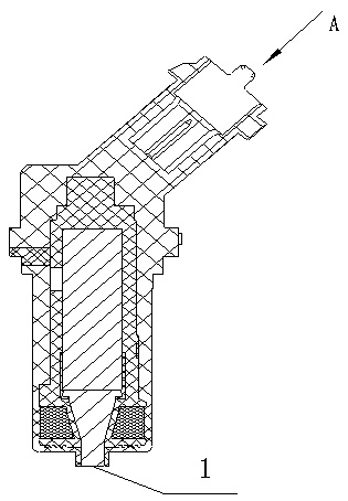
[0019] Crankshaft speed sensor main assembly as Figure 1 to Figure 5 shown. The bottom end of the crankshaft speed sensor body assembly is the end face 1 to be processed. The C surface is the positioning surface. The distance from the C surface to the bottom end surface 2 is dimension E. The axis from the C surface to the bottom end surface includes the D outer circle and the B outer circle.

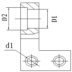
[0020] Crankshaft speed sensor main body assembly milling jig right body such as Figure 6 to Figure 8 shown. The upper part of the right body 3 is a right half step hole body, and the bottom part is a right base body, and the right base body is provided with two identical right step holes along the horizontal direction, and the hole direction of the right step hole is the same as that of the right half step hole body. vertical. The large hole diameter of the ri...


PUM


Abstract

The title of the present invention is a milling fixture for crankshaft speed sensor main body assembly. It belongs to the technical field of fixtures. It mainly solves the problem that the existing wire cutting process cannot meet the mass production of factories due to low production efficiency. Its main features are: including the right body and the left body; the upper part of the right body is the right half-step hole body, the lower part is the right seat body, and the right seat body is provided with two identical right step holes, and the hole direction of the right step hole is It is perpendicular to the hole direction of the right half-step hole body; the upper part of the left body is the left half-step hole body, the lower part is the left base body, and the left base body is provided with two identical left step holes, and the left step hole is aligned with the left The hole direction of the half-step hole body is vertical; the right base body is the same as the left base body, and the right half-step hole body and the left half-step hole body have the same size and opposite directions. The invention has the characteristics of quickness, convenience and high processing efficiency, and is mainly used for the milling process of the main body assembly of the crankshaft speed sensor and the similar ABS body assembly whose shape of the clamping end cannot be clamped.

Description

technical field [0001] The invention belongs to the technical field of fixtures for crankshaft speed sensors, and in particular relates to a milling fixture for a main body assembly of a crankshaft speed sensor. Background technique [0002] At present, the requirements for engine emissions are getting higher and higher, and the emissions must meet the requirements of Euro III or National IV. The present invention is aimed at a milling fixture for Euro III Weichai crankshaft speed sensor main body assembly. Since the main body assembly of the crankshaft speed sensor is molded several times, it is necessary to leave the necessary intermediate metal mandrel process head for this process during injection molding, but this process head must be removed after the final molding. Since the main body assembly of the crankshaft speed sensor has a complex shape after injection molding, the three-jaw chuck or spring collet on the lathe cannot clamp the main body assembly, so that the t...

Claims


Application Information

Patent Timeline
Patent Type & Authority Patents(China)
IPC IPC(8): B23Q3/06
Inventor 金青锋卢平侯斐程贵祥
Owner DONGFENG AUTOMOBILE ELECTRONICS
Why Eureka
Try Eureka