Automatic cutting machining device for spherical surface roller

A cutting and spherical roller technology, applied in metal processing equipment, metal processing mechanical parts, manufacturing tools, etc., can solve the problems of low processing efficiency and unstable dimensions, and achieve convenient operation, compact structure and high processing accuracy. Effect

Active Publication Date: 2012-01-04
WUXI YITONG PRECISION MACHINERY
View PDF0 Cites 0 Cited by
  • Summary
  • Abstract
  • Description
  • Claims
  • Application Information

AI Technical Summary

Problems solved by technology

[0003] In view of the above defects, the purpose of the present invention is to provide an automatic cutting device with a compact structure, adopts a casting box structure, and can improve the processing accuracy, so as to solve the defects of low processing efficiency and insufficient size stability in the prior art

Method used


Image

  • Automatic cutting machining device for spherical surface roller
  • Automatic cutting machining device for spherical surface roller

Examples


Embodiment Construction

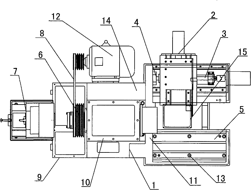
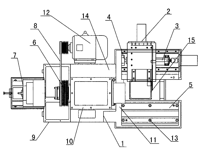
[0011] like figure 1 As shown, the automatic cutting processing device for spherical rollers of the present invention includes a casting box bed 1, a transmission assembly 6, an axle box 10, a feeding mechanism 11, and a clamping mechanism 15. The casting box bed The upper left part of the body 1 is provided with an axle box 10, and a transmission assembly 6 is installed in the housing 9 on one side of the axle box 10. The transmission assembly 6 is connected with the motor drive mechanism 12 outside the housing 9 through a transmission rod 8, and the transmission The other side of the shell of the assembly 6 is provided with a blanking mechanism 7; the lower side of the axle box 10 is a processing unit 14 composed of a cutting head, a numerical control tool holder, a workpiece processing mechanism, etc., and one side of the processing unit 14 is installed with a clamp Clamping mechanism 15, the bed tail of the clamping mechanism 15 is provided with a frame body 5 fixed by bol...


PUM


Abstract

The invention relates to an automatic cutting machining device for a spherical surface roller, comprising a cast box type bed body, a driving assembly, a shaft box, a feeding mechanism and a clamping mechanism. The left upper part of the cast box type bed body is provided with the shaft box, the driving assembly is arranged in a shell of one side of the shaft box and is connected with a motor driving mechanism outside the shell by a driving rod, the lower side of the shaft box is provided with a processing unit consisting of a cutting head, a numeric control cutter frame, a workpiece processing mechanism, and the like, the feeding mechanism is arranged between the shaft box and the frame body, and a rolling shaft mechanism is arranged on the other side of the clamping mechanism. The automatic cutting machining device for the spherical surface roller has compact structure and convenient operation, adopts the structures of a linear sliding guide rail and a ball screw rod and has higher machining precision and stable processing size, and the surface roughness of processing members conforms to a standard.

Description

technical field [0001] The invention relates to the field of machine tools, in particular to an automatic cutting device for spherical rollers. Background technique [0002] The overall structure of the roller processing machine tool is generally composed of a bed, a spindle box, a clamping mechanism, a feeding mechanism, a tool holder, etc., and the local structure also includes a spindle box, a gearbox, a hanging wheel box, a feed box, a slide Crates, knife holders, bed saddles, turntables, tailstocks, screw rods, motor drive mechanisms, etc. Among them, the spindle box is used to support the spindle and make it rotate at various speeds. The general spindle is hollow, which is convenient for processing operations through long workpieces. The tip can be installed at the front end of the spindle by using a taper hole, or the cone at the front end of the spindle can be used. Install the chuck and dial on the surface to clamp the workpiece; the existing roller cutting machine...

Claims


Application Information

Patent Timeline
Patent Type & Authority Patents(China)
IPC IPC(8): B23Q1/00
Inventor 何民权
Owner WUXI YITONG PRECISION MACHINERY
Why Eureka
Try Eureka