Proportional Pressure Brake Control Valve

A pressure control and proportional technology, applied in the direction of control valves, air release valves, brakes, brake components, etc., can solve problems such as large outlet pressure, increased electromagnet output force, complex structure of electro-hydraulic servo valves, etc., to achieve reduction Small size and weight, the effect of reducing the output force

Active Publication Date: 2017-05-31
BEIHANG UNIV
View PDF4 Cites 0 Cited by
  • Summary
  • Abstract
  • Description
  • Claims
  • Application Information

AI Technical Summary

Problems solved by technology

[0003] In the 1970s, the electro-hydraulic servo valve control technology became more and more mature. However, due to the complex structure of the electro-hydraulic servo valve, there is a pilot leakage, high manufacturing precision requirements, high price, very sensitive to oil pollution, and high requirements for the use and maintenance of the system. difficult to be widely accepted
[0007] Generally speaking, the outlet pressure Po is very large. According to the formula (1), it can be seen that when Po increases, the output force F of the electromagnet will be greatly increased. 电 , thereby increasing the volume and weight of the electromagnet

Method used


Image

  • Proportional Pressure Brake Control Valve
  • Proportional Pressure Brake Control Valve
  • Proportional Pressure Brake Control Valve

Examples


Embodiment Construction

[0030] Embodiments of the present application are described below with reference to the drawings. Elements and features described in one drawing or one embodiment of the present application may be combined with elements and features shown in one or more other drawings or embodiments. It should be noted that representation and description of components and processes that are not relevant to the present application and known to those of ordinary skill in the art are omitted from the drawings and descriptions for the purpose of clarity.

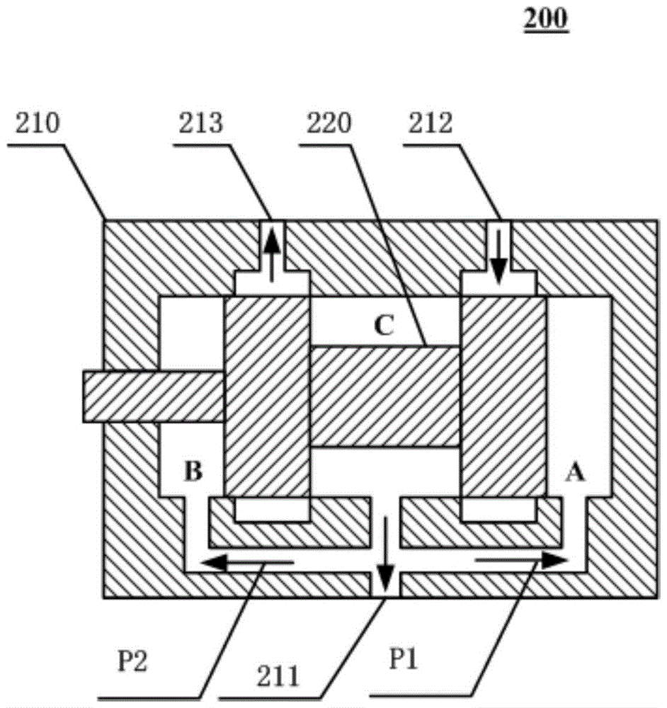
[0031] see figure 2 Shown is a schematic structure diagram 200 of an embodiment of the proportional pressure control valve of the present application.

[0032] In this embodiment, the proportional pressure control valve includes a valve body 210 and an asymmetric piston 220 located in the valve body.

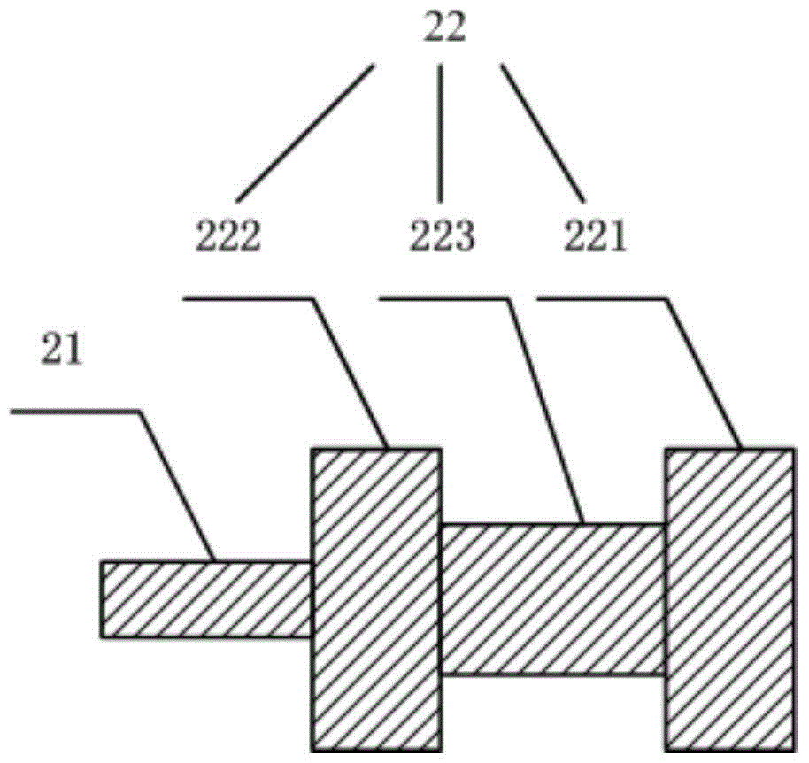
[0033] see image 3 shown, for figure 2 A schematic structural diagram of the asymmetric piston 220 in .

[0034] The asymmetric piston 22...


PUM


Abstract

The invention relates to a proportional pressure brake control valve which comprises a valve body and an asymmetric piston located in the valve body. The Asymmetric piston comprises a cylindrical part and a piston part which is vertically and fixedly connected with the cylindrical part; the piston part comprises a first piston body, a second piston body and a fixed shaft which is fixedly connected between the first piston body and the second piston body; a first oil return channel is formed between the firs piston body and the inner wall of the valve body, and a second oil return channel is formed between the second piston body and the inner wall of the valve body; the first oil return channel is communicated with a first chamber formed by the valve body and the first piston body, and the second oil return channel is communicated with a second chamber formed by the valve body and the second piston body. With the adoption of the proportional pressure brake control valve, output force of a driving mechanism can be reduced, and the size and the weight of the driving mechanism are reduced accordingly.

Description

technical field [0001] The application relates to the technical field of hydraulic pressure and fluid transmission, in particular to a proportional pressure brake control valve. Background technique [0002] The electro-hydraulic proportional valve is the key control device to realize the electro-hydraulic proportional control technology. Due to its better control accuracy and stability, the electro-hydraulic proportional valve has gradually replaced the traditional servo valve. The electro-hydraulic proportional pressure control valve is an electro-hydraulic proportional valve. One of them, its function is to control the oil pressure in the hydraulic system proportionally, and then realize the proportional control of the output force or output torque of the actuator. [0003] In the 1970s, the electro-hydraulic servo valve control technology became more and more mature. However, due to the complex structure of the electro-hydraulic servo valve, there is a pilot leakage, hig...

Claims


Application Information

Patent Timeline
Patent Type & Authority Patents(China)
IPC IPC(8): B60T15/18
CPCB60T15/185
Inventor 焦宗夏李冰尚耀星刘晓超
Owner BEIHANG UNIV
Why Eureka
Try Eureka