Fluid proportioning valve with pressure balancing device and application thereof

A technology of balancing devices and proportioning valves, which is applied in the direction of valve devices, multi-way valves, engine components, etc., can solve problems such as prone to failure, large manpower, material resources, valve core and pipeline blockage, and achieve non-linear adjustment problems Simplify, improve production efficiency, and ensure the effect of operation accuracy

Active Publication Date: 2016-01-06
SHANDONG UNIV OF SCI & TECH
View PDF7 Cites 3 Cited by
  • Summary
  • Abstract
  • Description
  • Claims
  • Application Information

AI Technical Summary

Problems solved by technology

This traditional process has the following disadvantages: (1) if the solution is volatile, it is not conducive to the mixing operation in advance, and it will also cause bodily harm to the operator; (2) if the A and B solutions can produce chemical reactions, the traditional process The real-time performance of the method is poor, and the use performance of the mixed solution cannot be achieved; (3) the mixed solution needs manual replenishment and filling, which is easy to cause human error and affect product quality; (4) this method consumes a lot of manpower and material resources, and has poor reliability
[0003] At present, adopting liquid mixing proportioning valve is a commonly used solution, such as the more commonly used water mixing valve, but there are some problems in the existing water mixing valve: (1) the existing water mixing valve adopts thermal elements to Cold water and hot water are mixed to ensure a constant temperature of the outlet water. The water mixing valve adopts a check valve to prevent water from passing through. The structure is complex, the cost is high, and it is prone to failure; control, rather than the control of the solution ratio; (3) the existing mixing valve controls the ratio adjustment and flow adjustment by using the same operating handle in different directions of movement, and this linkage method increases the difficulty of use by the operator; (4) The existing mixing valve sets the valve at the rear end of the mixing chamber, which leads to the problem of cross-flow of the A and B solutions, which easily causes the solutions to undergo chemical reactions in advance to produce crystalline solids, resulting in blockage of the valve core and pipes (5) The existing mixing valve adopts a circular valve port, and the output flow of this form of valve port has a nonlinear relationship with the valve core displacement, and the operator cannot accurately control the mixing ratio of the output solution, let alone set the scale indication; (6) The existing mixing valve simply mixes the solutions, and cannot adjust and control the change of the input pressure, which leads to the mixing ratio of the output solution being significantly affected by the pressure change, and it is impossible to maintain a constant ratio of the output solution. Purpose; (7) The existing mixing valve has no output protection function, that is, when the input flow rate of one of the two solutions is zero, the outlet will continue to output, and the valve port cannot be automatically closed

Method used


Image

  • Fluid proportioning valve with pressure balancing device and application thereof
  • Fluid proportioning valve with pressure balancing device and application thereof
  • Fluid proportioning valve with pressure balancing device and application thereof

Examples


Embodiment 1

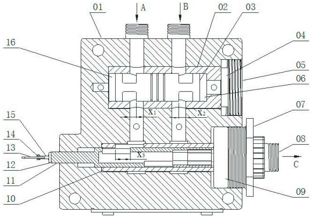
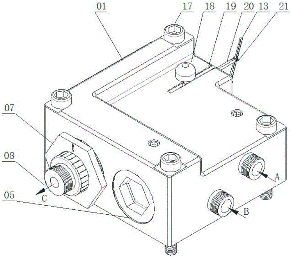
[0065] A fluid proportioning valve with a pressure balance device, comprising a housing 01, a first valve chamber and a second valve chamber are arranged in the housing 01, and the first valve chamber and the second valve chamber are communicated through two flow passages , A fluid inlet 0102, B fluid inlet 0103 communicated with the first valve chamber, and a mixed fluid C outlet communicated with the second valve chamber are opened on the housing;

[0066] A pressure balance valve body 02 is provided in the first valve chamber, a pressure balance valve core 03 is provided in the pressure balance valve body 02, and a pressure balance plug 05 is provided at one end of the first valve chamber for connecting the pressure balance valve core 03 And the pressure balance valve body 02 is installed in the first valve cavity, the first valve cavity is provided with A pressure balance inlet 0101 and B pressure balance inlet 0104, and the pressure balance valve body 02 is equipped with A...

Embodiment 2

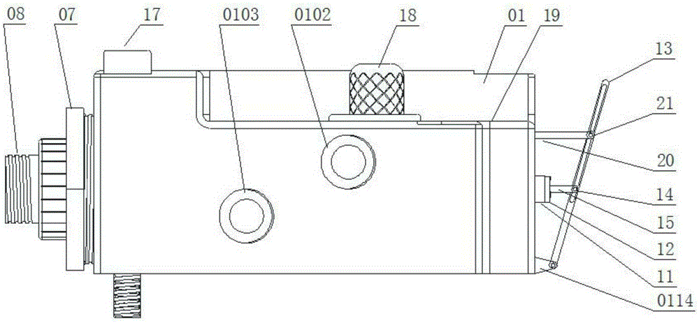
[0076] A fluid proportioning valve with a pressure balance device, the structure is as described in Embodiment 1, the difference is that the fluid proportioning valve also includes an adjustment lever 13, and one end of the central valve core 11 protrudes from the housing and is provided with The swivel joint 12 is hinged to the adjustment lever 13 through the fork 15 of the small arm, and the bottom end of the adjustment lever 13 is hinged to the housing 01 .

[0077] The upper part of the adjustment lever 13 is also hinged with a large arm shift fork 20, which is embedded in the housing 01 and can move in the housing. A flow adjustment scale 19 is arranged on the side of the boom shift fork 20 on the housing. Through the combination of the flow adjustment scale 19 and the arm shift fork 20, the linear displacement of the adjustment central valve core 11 can be observed intuitively, and the displacement of the central valve core can be adjusted conveniently and accurately.

...

Embodiment 3

[0080] This embodiment provides a method for using the fluid proportioning valve with a pressure balance device as described in Embodiment 2, including the following steps,

[0081] (1) Solution A is input into housing 01 through A fluid inlet 0102, and its supply pressure is P A; Solution B is input into housing 01 through B fluid inlet 0103, and its supply pressure is P B ;

[0082] (2) The solution A continues to flow through the A pressure balance inlet 0101, and after passing through the pressure balance unit composed of the pressure balance valve body 02 and the pressure balance valve core 03, it is output through the A pressure balance outlet 0116. At this time, the output pressure is P AO ;The solution B continues to flow through the B pressure balance inlet 0104, and after passing through the pressure balance unit composed of the pressure balance valve body 02 and the pressure balance valve core 03, it is output through the B pressure balance outlet 0108. At this tim...


PUM


Abstract

The invention relates to a fluid proportioning valve with a pressure balancing device and an application thereof. The fluid proportioning valve comprises a shell, wherein a first valve cavity and a second valve cavity which are connected are formed in the shell; a pressure balancing unit is arranged in the first valve cavity; a center valve body and a center valve core are arranged in the second valve cavity; a valve body inlet A and a valve body inlet B are formed in the center valve body; a valve core inlet A and a valve core inlet B which are respectively matched with the valve body inlet A and the valve body inlet B are formed in the center valve core; and the flow areas of fluid A and fluid B are adjusted by rotating the angle of the center valve core in the center valve body, further the proportioning of the two fluids is adjusted, and the outflow of mixed fluid is adjusted by linear displacement of the center valve core. The fluid proportioning valve can set the volume ratio of the fluids after mixing at random, meanwhile can adjust the outflow of the mixed fluid and is relatively high in efficiency and good in timeliness.

Description

technical field [0001] The invention relates to a fluid proportioning valve with a pressure balance device and its application, belonging to the technical field of valves. Background technique [0002] At present, it is often encountered in the production line of the factory that the two solutions of A and B need to be mixed in proportion. The traditional process is to mix the two solutions in a large container in advance according to the volume ratio, and slowly drop them in when they are ready to use. This traditional process has the following disadvantages: (1) if the solution is volatile, it is not conducive to the mixing operation in advance, and it will also cause bodily harm to the operator; (2) if the A and B solutions can produce chemical reactions, the traditional process The real-time performance of the method is poor, and the use performance of the mixed solution cannot be achieved; (3) the mixed solution needs to be manually replenished and filled, which is easy...

Claims


Application Information

Patent Timeline
Patent Type & Authority Applications(China)
IPC IPC(8): F16K11/07F16K37/00
CPCF16K11/07F16K37/0016
Inventor 万丽荣逯振国曾庆良许德山李伟民孟昭胜岳宗兴王认辉杨延超杨扬张世奇李旭孔帅崔晶
Owner SHANDONG UNIV OF SCI & TECH
Why Eureka
Try Eureka