A Flow Regulating Proportioning Valve and Its Application

A technology of flow regulation and proportioning valves, applied in the direction of valve details, multi-way valves, valve devices, etc., can solve problems such as prone to failure, valve core and pipeline blockage, cost a lot of manpower and material resources, and achieve non-linear adjustment problems Simplify, ensure operation accuracy, and improve production efficiency

Active Publication Date: 2016-08-17
SHANDONG UNIV OF SCI & TECH
View PDF6 Cites 0 Cited by
  • Summary
  • Abstract
  • Description
  • Claims
  • Application Information

AI Technical Summary

Problems solved by technology

This traditional process has the following disadvantages: (1) if the solution is volatile, it is not conducive to the mixing operation in advance, and it will also cause bodily harm to the operator; (2) if the A and B solutions can produce chemical reactions, the traditional process The real-time performance of the method is poor, and the use performance of the mixed solution cannot be achieved; (3) the mixed solution needs manual replenishment and filling, which is easy to cause human error and affect product quality; (4) this method consumes a lot of manpower and material resources, and has poor reliability
[0003] At present, adopting liquid mixing proportioning valve is a commonly used solution, such as the more commonly used water mixing valve, but there are some problems in the existing water mixing valve: (1) the existing water mixing valve adopts thermal elements to Cold water and hot water are mixed to ensure a constant temperature of the outlet water. The water mixing valve adopts a check valve to prevent water from passing through. The structure is complex, the cost is high, and it is prone to failure; control, rather than the control of the solution ratio; (3) the existing mixing valve controls the ratio adjustment and flow adjustment by using the same operating handle in different directions of movement, and this linkage method increases the difficulty of use by the operator; (4) The existing mixing valve sets the valve at the rear end of the mixing chamber, which leads to the problem of cross-flow of the A and B solutions, which easily causes the solutions to undergo chemical reactions in advance to produce crystalline solids, resulting in blockage of the valve core and pipes (5) The existing mixing valve adopts a circular valve port, the output flow of this form of valve port has a nonlinear relationship with the displacement of the valve core, and the operator cannot accurately control the mixing ratio of the output solution, let alone set the scale indication

Method used


Image

  • A Flow Regulating Proportioning Valve and Its Application
  • A Flow Regulating Proportioning Valve and Its Application
  • A Flow Regulating Proportioning Valve and Its Application

Examples


Embodiment 1

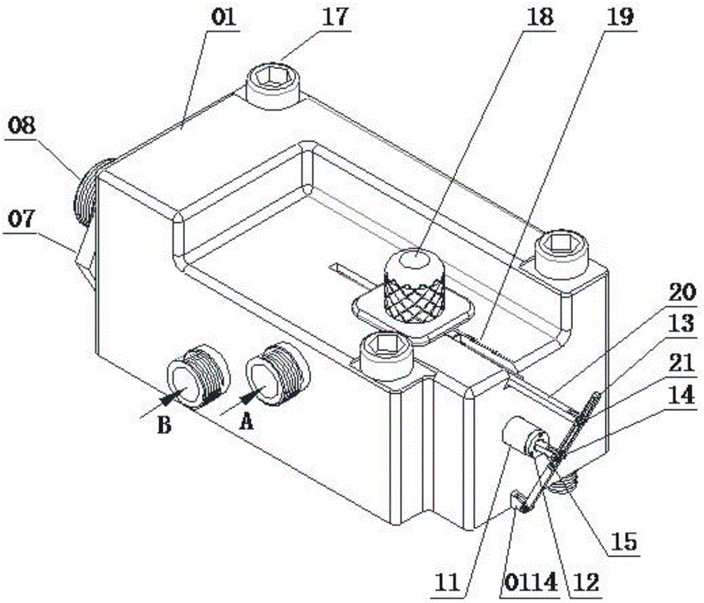
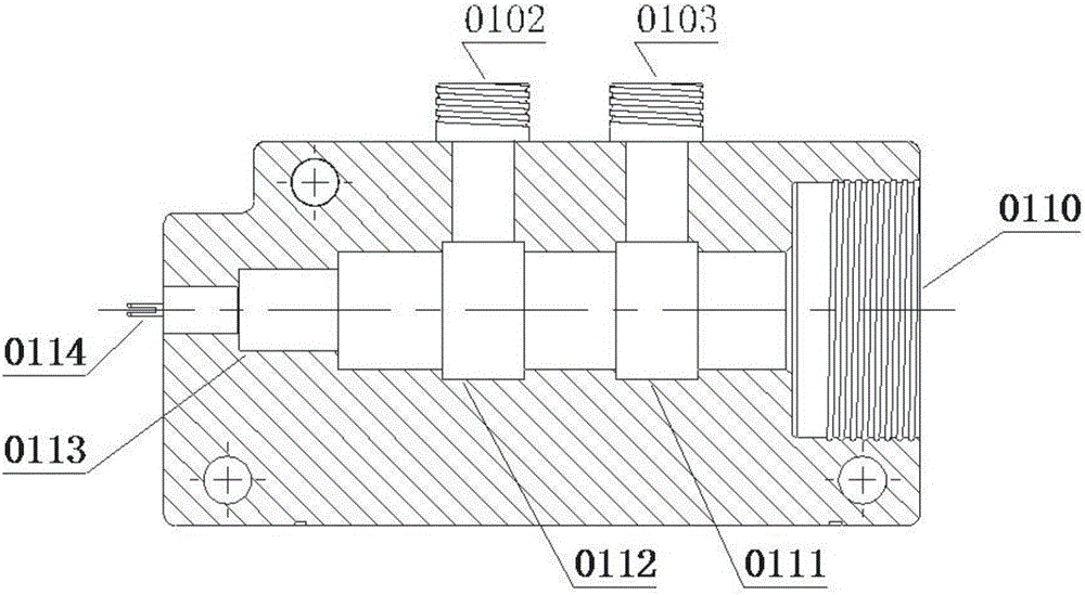
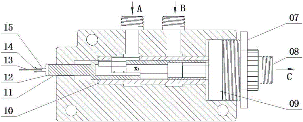
[0051] A flow adjustment proportioning valve, comprising a housing 01, a valve cavity is provided in the housing 01, and the A fluid inlet 0102, the B fluid inlet 0103 and the mixed fluid C are opened on the housing 01 and communicated with the valve cavity. Outlet; a central valve body 10 is arranged in the valve cavity, and a central valve core 11 is arranged in the central valve body 10. The central valve core 11 includes a mixing chamber 1104, and one end of the mixing chamber 1104 communicates with the outlet of the mixed fluid C, and the central valve body 10 is provided with an A valve body inlet 1001 and a B valve body inlet 1002, and the central valve core 11 is provided with an A valve core inlet 1101 and a B valve core inlet 1102 respectively matched with the A valve body inlet 1001 and the B valve body inlet 1002 , and both the A spool inlet 1101 and the B spool inlet 1102 communicate with the mixing chamber 1104, and the A spool inlet 1101 and the A valve body inle...

Embodiment 2

[0057] A flow regulating proportional valve, the structure is as described in Embodiment 1, the difference is that: the flow regulating proportional valve also includes an adjusting lever 13, one end of the central valve core 11 protrudes from the housing and is provided with a rotary joint 12, The swivel joint 12 is hinged to the adjustment lever 13 through the fork 15 of the small arm, and the bottom end of the adjustment lever 13 is hinged to the lever fulcrum 0114 on the housing 01 .

[0058] The upper part of the adjustment lever 13 is also hinged with a large arm shift fork 20, which is embedded in the housing 01 and can move in the housing. A flow adjustment scale 19 is arranged on the side of the boom shift fork 20 on the housing. Through the combination of the flow adjustment scale 19 and the arm shift fork 20, the linear displacement of the adjustment central valve core 11 can be observed intuitively, and the displacement of the central valve core can be adjusted conv...

Embodiment 3

[0061] This embodiment provides a method for using the flow regulating proportional valve as described in Embodiment 2, which includes the following steps,

[0062] (1) Two solutions A and B with equal pressure, solution A is input into the housing 01 through the A fluid inlet 0102, and solution B is input into the housing 01 through the B fluid inlet 0103;

[0063] (2) The solution A continues to flow into the central inlet 0112 of A, and passes through the rectangular cross-sectional area S formed by the two rectangular valve ports of the A valve body inlet 1001 and the A valve core inlet 1101 A After entering the mixing chamber 1104, it is output through the output threaded joint 0802 at the right end of the proportioning adjustment handle 08; the solution B continues to flow into the B center inlet 0111, and passes through the rectangular valve port formed by the B valve body inlet 1002 and the B valve core inlet 1102 Flow cross-sectional area S B , enter the mixing chamb...


PUM


Abstract

The invention relates to a proportioning valve with the flow regulation function and application thereof. The proportioning valve with the flow regulation function comprises a case body. A valve cavity is formed in the case body. The case body is provided with a fluid A inlet, a fluid B inlet and a mixed fluid C outlet, wherein the fluid A inlet, the fluid B inlet and the mixed fluid C outlet are communicated with the valve cavity. A central valve body and a central valve core are arranged in the valve cavity. The central valve core comprises a mixing cavity. The central valve body is provided with an A valve body inlet and a B valve body inlet. The central valve core is provided with an A valve core inlet and a B valve core inlet, wherein the A valve core inlet and the B valve core inlet are communicated with the mixing cavity. Through angle rotation of the central valve core in the central valve body, the through-flow sectional area of the A valve core inlet and the A valve body inlet and the through-flow sectional area of the B valve core inlet and the B valve body inlet can be regulated, then proportioning of fluid A and fluid B can be regulated, and the outflow volume of mixed fluid C can be regulated through linear displacement of the central valve core in the central valve body. According to the invention, the volume and the proportion of the mixed fluid can be set freely, the outflow volume of the mixed fluid can be regulated, the efficiency is higher and the timeliness is high.

Description

technical field [0001] The invention relates to a flow regulating proportional valve and its application, belonging to the technical field of valves. Background technique [0002] At present, it is often encountered in the production line of the factory that the A and B solutions need to be mixed in proportion. The traditional process is to mix the two solutions in a large vessel in advance according to the volume ratio, and slowly drop them in when they are ready to use. This traditional process has the following disadvantages: (1) if the solution is volatile, it is not conducive to the mixing operation in advance, and it will also cause bodily harm to the operator; (2) if the A and B solutions can produce chemical reactions, the traditional process The real-time performance of the method is poor, and the use performance of the mixed solution cannot be achieved; (3) the mixed solution needs to be manually replenished and filled, which is easy to cause human error and affect...

Claims


Application Information

Patent Timeline
Patent Type & Authority Patents(China)
IPC IPC(8): F16K11/085F16K31/60
CPCF16K11/085F16K31/60
Inventor 万丽荣逯振国曾庆良王成龙李伟民许德山岳宗兴张晓东杨延超王小环王刚李旭王统诚
Owner SHANDONG UNIV OF SCI & TECH
Why Eureka
Try Eureka