
Fast connection mechanism

A technology of quick connection and connection end, which is applied in the direction of mechanical equipment, couplings, etc., can solve the problems of not tight clamping of the connection pipe, non-adjustable parts, non-replaceable parts, etc., to achieve enhanced firmness and stability, replacement and maintenance costs Low cost and high product assembly yield

Active Publication Date: 2016-01-06
许道泽
View PDF11 Cites 6 Cited by
  • Summary
  • Abstract
  • Description
  • Claims
  • Application Information

AI Technical Summary

Problems solved by technology

However, in the production process, there are high precision requirements for the position of the parts before injection molding in the mold
After the injection molding is completed, because the parts are all covered in the body, the internal parts of the quick connector cannot be adjusted and cannot be replaced. It may be that the parts are not installed properly before injection molding, leaving a gap between the parts, causing the snap ring Shaking, which causes the snap ring to be unable to hold the connecting pipe stably
In addition, in the actual use process, because the clip teeth of the snap ring are always squeezed by the outer wall of the connecting pipe and turned to the inside of the quick joint, after long-term use, the clip teeth will lose the elastic restoring force of shrinking in the axial direction and clamping the connecting pipe. As a result, there are situations where the clamping of the connecting pipe is not tight, the shaking of the connecting pipe and the sealing effect are not good

Method used


Image

  • Fast connection mechanism
  • Fast connection mechanism
  • Fast connection mechanism

Examples


Embodiment Construction

[0029] The following are specific embodiments of the present invention and in conjunction with the accompanying drawings, the technical solutions of the present invention are further described, but the present invention is not limited to these embodiments.

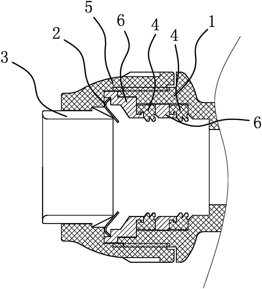
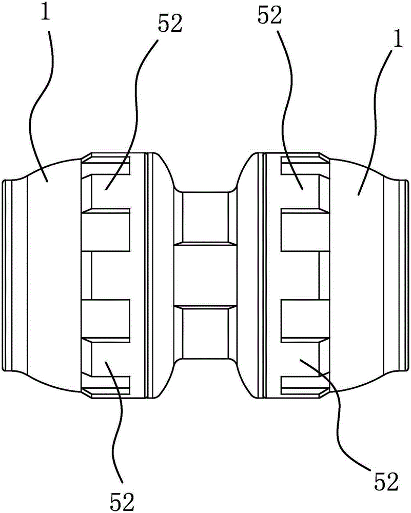
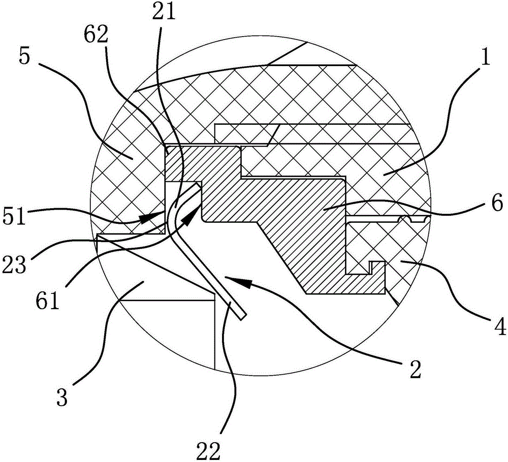
[0030] Such as figure 1 , image 3 , Figure 4 , Figure 5 and Figure 6 As shown, the quick connection mechanism is set at the cylindrical connecting end 1 on the shell, including a snap ring 2, a cylindrical intubation tube 3 and a ring-shaped seal set on the inner wall of the connecting end 1. Circle 4. Wherein, the snap ring 2 includes a ring-shaped collar portion 21 and a plurality of locking teeth portions 22 evenly distributed on the inner edge of the collar portion 21 , and the locking teeth portions 22 and the collar portion 21 are connected as a whole. The locking tooth part 22 is arranged obliquely in a direction away from the port of the connecting end 1, that is, the outer end of the locking tooth part 22...


PUM

PropertyMeasurementUnit
Central angleaaaaaaaaaa

Abstract

The invention provides a fast connection mechanism, belongs to the technical filed of machinery and solves the problems that the clamping of connecting pipes is not tight, the connecting pipes are loosened and the sealing effect is poor after long time use of existing fast joints. The fast connection mechanism is arranged at the connecting end of a shell and comprises an inserting pipe, a seal ring and a clamping ring which is arranged between the inserting pipe and the seal ring; the clamping ring comprises an annular clamping ring portion and a plurality of clamping teeth portions which are distributed at the inner edge of the clamping ring portion; the end, not connected with the clamping ring portion, of each clamping tooth portion is inclined towards one side of the seal ring; the inner end of the inserting pipe can abut against the side, facing the inserting pipe, of each clamping tooth portion. The fast connection mechanism further comprises a nut; the inner side of the nut is provided with a first extruding surface; the clamping ring portion is located on the inner side of the first extruding surface; the clamping ring portion bends towards one side of the first extruding surface to form a protruding bent angle, and the side, opposite to the first extruding surface, of the bent angle abuts against the first extruding surface. The fast connection mechanism is firm in connection, good in sealing effect and low in replacement and maintenance cost.

Description

technical field [0001] The invention belongs to the technical field of machinery and relates to a quick connection mechanism. Background technique [0002] The application of quick connectors makes the pipeline connection technology more mature, especially the in-line quick connectors, which are widely used in daily life and industrial production equipment. Compared with the connection method of hot melter, the in-line quick connector has high connection strength and good shock resistance. The connection part is disposable, and the greater the pressure in the pipe, the inner diameter of the pipe will expand and the buckle will be tighter, avoiding loosening and There is no possibility of water leakage, and there is no need for hot melting, which avoids the laborious construction of on-site welding operations, and the installation is faster. [0003] The applicant designed a quick connector and applied for a Chinese patent [its application number is: 201210271931.6; its anno...

Claims


Application Information

Patent Timeline
IPC IPC(8): F16L37/12
CPCF16L37/12
Inventor 许道泽
Owner 许道泽
Learn More