Pipe network leak detecting method in combination with resistance identification

A leak detection and pipe network technology, which is applied in pipeline systems, mechanical equipment, gas/liquid distribution and storage, etc., can solve the problems of artificial neural network method such as small number of samples, difficult automatic monitoring system integration, a large number of instruments and equipment manpower, etc. , to achieve the effect of reducing the labor intensity of manual inspection, reducing the inspection time, and reducing the cost of leak detection

Inactive Publication Date: 2016-01-06
HARBIN INST OF TECH
View PDF4 Cites 16 Cited by
  • Summary
  • Abstract
  • Description
  • Claims
  • Application Information

AI Technical Summary

Problems solved by technology

[0005] In order to solve the problem that the passive leak detection method mainly requires a large amount of equipment and manpower, it is difficult to combine with the automatic monitoring system, and the artificial neural network method has a small number of samples, which causes large deviations in the optimization results and takes a long time.

Method used


Image

  • Pipe network leak detecting method in combination with resistance identification
  • Pipe network leak detecting method in combination with resistance identification
  • Pipe network leak detecting method in combination with resistance identification

Examples


specific Embodiment approach 1

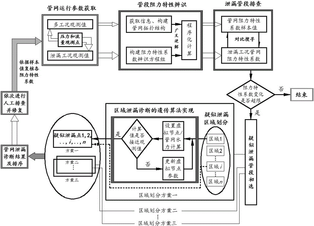
[0032] Specific implementation mode one: combine figure 1 To describe this embodiment,

[0033] A pipe network leak detection method combined with resistance identification, comprising the following steps:

[0034] Step 1. Obtain topological structure: By collecting design materials such as design and construction drawings of water supply or gas supply (heat supply) pipe network systems, obtain information on nodes and pipe sections of the pipe network system, that is, topological structure; among them, nodes, pipe sections, and resistance characteristic systems are involved. Count three concepts: node refers to the connection node at the branch of the pipe network, and the flow rate of the pipe segment connected to the node is different; the pipe segment generally refers to a pipe segment, and there is actually a branch at the connection of two pipe segments but there is no leakage at the branch, that is to say Two connected pipe sections with the same flow rate are also reg...

specific Embodiment approach 2

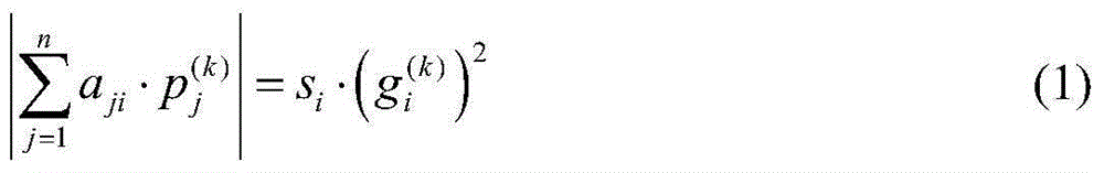
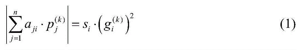
[0052] The process of establishing a system of equations including resistance characteristic coefficients described in step 2 of the present embodiment is as follows,

[0053] The resistance characteristic coefficient equation is shown in formula (1)

[0054] | Σ j = 1 n a j i · p j ( k ) | = s i · ( g i ( k ) ) 2 - - - ( 1 )

[0055] In the formula, i is the serial number of th...

specific Embodiment approach 3

[0058] The process of finding out the pipe section whose variation range exceeds the set value described in step 2 of this embodiment is as follows,

[0059] Under some different working conditions, the change of the resistance characteristic coefficient of the pipe section is caused by observation errors. The limit value is considered to be suspected of leakage; the degree of influence of leakage on the resistance characteristic coefficient of the pipe section is not only affected by the leakage itself, but also related to the pipe diameter. The allowable change range of the resistance coefficient of the pipe section under the suspected leakage condition is as follows:

[0060] For a pipe section with a pipe diameter of 100-200mm, the allowable change range is [0, 50%] of the set value of the resistance coefficient of the corresponding pipe section under normal working conditions;

[0061] For a pipe section with a pipe diameter of 250-400mm, the allowable variation range is ...


PUM


Abstract

The invention discloses a pipe network leak detecting method in combination with resistance identification, relates to pipe network leak detecting methods and aims to solve the problems that passive leakage control methods mainly need a large number of instruments, equipment and manpower and are hardly combined with automatic monitored control systems, and large deviation of optimization results due to a small number of samples and long consuming time exist in artificial neural network methods. The pipe network leak detecting method in combination with resistance identification includes that firstly, pressure observed values of flow nodes of part of pipe sections are used as known conditions; an equation set containing pipe section resistance information is established; resistance results are expressed through generalized inverse solution of the equation set. Then, a pipeline where leakage possibly occurs is divided into a plurality of different areas; in each area, observed values of operation parameters of an edge pipe network are used as known conditions, virtual nodes are introduced to represent leakage points, and specific positions and leakage flow of the virtual nodes are determined by the aid of genetic algorithm optimization; accordingly, leakage is positioned and quantified. Then sequential manual troubleshooting and re-checking is performed. The pipe network leak detecting method in combination with resistance identification is applicable to the field of pipe network leak detection.

Description

technical field [0001] The invention relates to a pipeline network leakage detection method. Background technique [0002] Pipeline leak detection methods can be divided into two broad categories, namely passive leak detection methods and active leak detection methods. The passive leak detection method is relatively straightforward, and most of them need to use instruments and equipment with certain detection functions for leak detection; while the active leak detection method mainly relies on the daily monitoring data of the pipeline network, and uses effective analysis methods for leak detection. [0003] Passive leak detection methods mainly include manual inspection method, isolation method, listening method and temperature measurement method. The manual inspection method needs to organize a special team to inspect the pipeline, which depends on the sensitivity, experience and sense of responsibility of the personnel, and only some large leaks can be found. The isolati...

Claims


Application Information

Patent Timeline
Patent Type & Authority Applications(China)
IPC IPC(8): F17D5/02
Inventor 刘永鑫
Owner HARBIN INST OF TECH
Why Eureka
Try Eureka