

Running form evaporator for ice machine
A flowing water evaporator technology, applied in the field of flowing water evaporators for ice making machines, can solve the problems of ice cube hardness, different shapes, not necessarily accurate water intake, and high manufacturing costs, and achieve better product design and layout. Simple and convenient production, ensure the effect of quality
- Summary
- Abstract
- Description
- Claims
- Application Information
AI Technical Summary
Problems solved by technology
Method used
Image

Examples
Embodiment
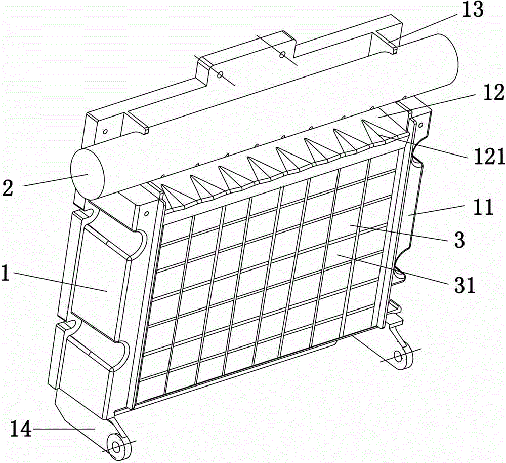
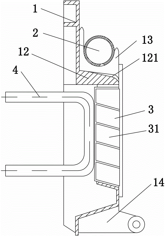
[0019] Embodiment: In the figure, the overflow port is arc-shaped on both sides and recessed in the middle to form a groove. The edge of the water spraying area is curved. The angle is the optimal angle of 72 degrees, which is convenient for the ice cubes to slide down automatically and collect them intensively.
[0020] Its working principle is: when the machine is working, the shower pipe 2 flows water slowly and evenly downwards, the water flows to the shower area 12, and flows into each corresponding ice tray through the center line of the concave notch of the overflow port 121, and the ice tray 3 The water in the ice tray is refrigerated by the evaporation tube 4 under the action of the refrigeration system, thereby forming ice cubes of the same size and hardness in the ice tray 3 . When it is necessary to take out the ice cubes, it is only necessary to increase the temperature of the evaporation tube 4, so that the ice cubes fall into the ice making box under the action ...
PUM
 Abstract
Description
Claims
Application Information