Debris flow moving and accumulating process simulation experiment system
What is Al technical title?
Al technical title is built by PatSnap Al team. It summarizes the technical point description of the patent document.
A technology for simulating experiments and debris flow. It is used in fluid dynamics tests, testing of machine/structural components, instruments, etc. It can solve the problems of low occurrence frequency of debris flow, large differences in debris flow characteristics, and difficulty in tracking debris flow. Difficulty and Dangerous Effects
Inactive Publication Date: 2016-01-06
JILIN UNIV
View PDF6 Cites 30 Cited by
Summary
Abstract
Description
Claims
Application Information
AI Technical Summary
This helps you quickly interpret patents by identifying the three key elements:
Problems solved by technology
Method used
Benefits of technology
Problems solved by technology
But mudslides occur less frequently, making it difficult to track ongoing mudslides
In addition, the characteristics of debris flow in different periods are quite different, and it is difficult to predict future debris flow parameters through the movement and accumulation parameters of individual periods of debris flow
Method used
Image
Click on the blue label to locate the original text in one second.
Reading with bidirectional positioning of images and text.
Examples
Embodiment Construction
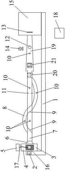
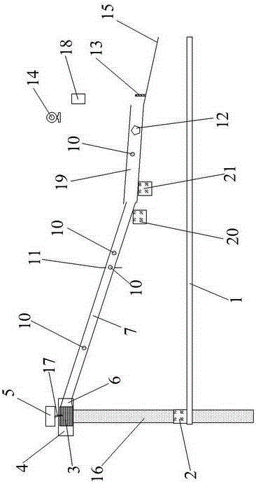
[0011] see figure 1 and figure 2 As shown, the present invention includes a conveyor belt 1, a first elevator 2, a second elevator 20, a third elevator 21, a stirring box 3, a working platform 4, a water tank 5, a connecting tank 6, a first direct-current channel 7, a second direct-current channel Groove 19, curved flow groove 8, flow groove valve 9, pore pressure test device 10, bayonet 11, flow rate and flow test device 12, impact force test device 13, high-speed camera 14, accumulation area 15, column foundation 16, pumping device 17 and receiving host 18; the working platform 4 is arranged on the column foundation 16 upper end, the mixing box 3 is placed on the working platform 4, the first elevator 2 is arranged beside the column foundation 16, and the upper end of the conveyor belt 1 is arranged on the first elevator 2 and is positioned at the stirring The upper part of the tank 3; the water tank 5 communicates with the stirring tank 3 through the pumping device 17; th...
PUM
Abstract
The invention discloses a debris flow moving and accumulating process simulation experiment system. The debris flow motion and accumulation process simulation experiment system comprises a conveyor belt, elevators, a stirring box, a work platform, a water tank, a connection groove, straight circulation grooves, a bent circulation groove, a circulation groove valve, hole pressure testing devices, a bayonet, a flow-speed and flow testing device, an impact force testing device, a high-speed camera, an accumulation area, a column base, a water drawing device and a receiving host. Solid particles with certain granularity compositions are prepared into a debris fluid with a certain slurry concentration by the conveyor belt, the elevators, the stirring box, the work platform, the water tank and the water drawing device, and the column base is used for ensuring the stability of the work platform. The circulation groove valve is used for controlling the debris fluid to move in the straight circulation grooves or the bent circulation groove. The elevators are used for controlling the moving gradient of the debris flow. Moving and accumulating processes and dynamics parameters of the debris flow are tested and monitored by the hole pressure testing devices, the flow-speed and flow testing device, the impact force testing device and the high-speed camera.
Description
technical field [0001] The invention relates to a mud-rock flow simulation device, in particular to a mud-rock flow movement and accumulation simulation experiment system. Background technique [0002] Debris flow is a common geological disaster in mountainous areas, which has the characteristics of sudden outbreak and huge destructive ability. Debris flows often carry huge boulders, which have a strong impact and endanger the lives and property of people passing through the area. Therefore, predicting the dynamic parameters and accumulation characteristics during the movement of debris flow has strong guiding opinions for disaster prevention and mitigation of debris flow. [0003] At present, the movement and accumulation parameters of debris flow are mainly obtained by on-site monitoring or actual measurement. But mudslides occur so infrequently that it's hard to keep track of ongoing mudslides. In addition, the characteristics of debris flow in different periods are qu...
Claims
Application Information
Patent Timeline
Application Date:The date an application was filed.
Publication Date:The date a patent or application was officially published.
First Publication Date:The earliest publication date of a patent with the same application number.
Issue Date:Publication date of the patent grant document.
PCT Entry Date:The Entry date of PCT National Phase.
Estimated Expiry Date:The statutory expiry date of a patent right according to the Patent Law, and it is the longest term of protection that the patent right can achieve without the termination of the patent right due to other reasons(Term extension factor has been taken into account ).
Invalid Date:Actual expiry date is based on effective date or publication date of legal transaction data of invalid patent.