
Universal interface modeling method for constructing interface model based on interface element model

A technology of interface model and meta-model, applied in the direction of program control devices, etc., can solve the problems of loss of diversity and flexibility of interface development, not allowing user-defined components, loss of readability of model view, etc., and shorten the modeling time , free from dependence and communication, the effect of a small number

Active Publication Date: 2016-01-06
CHENGDU PUZHONG SOFTWARE CO LTD
View PDF7 Cites 1 Cited by
  • Summary
  • Abstract
  • Description
  • Claims
  • Application Information

AI Technical Summary

Problems solved by technology

This method of graphical assembly based on prefabricated components naturally has two major disadvantages: first, it does not allow users to customize components, thereby limiting the possibility of user expression, thereby losing the diversity and flexibility required for interface development; second , when the interface function becomes complex, the model view assembled with prefab primitives becomes extremely complicated, especially the intersection of data lines makes the model view lose readability, so this method is usually only used for simple interface development , but cannot meet the needs of large-scale and complex interface development;
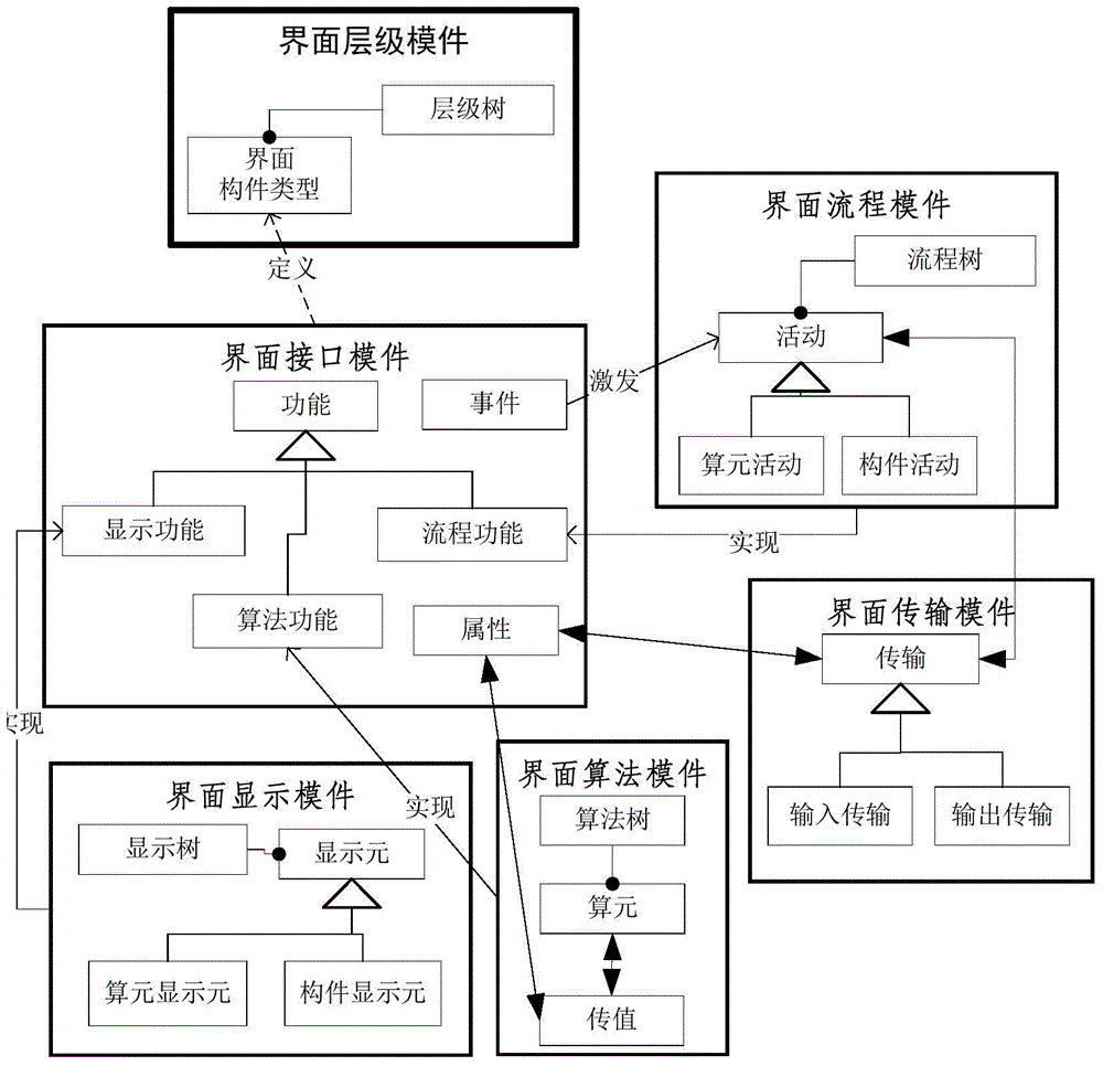
[0008] In general, there is still a lack of a universal, easy-to-use, and normative interface meta-model that can be easily understood and mastered by ordinary people in the field, and supports modeling activities of complex interface systems in various fields. Construct an interface model that can be automatically converted into computer-runable code

Method used


Image

  • Universal interface modeling method for constructing interface model based on interface element model
  • Universal interface modeling method for constructing interface model based on interface element model
  • Universal interface modeling method for constructing interface model based on interface element model

Examples


Embodiment

[0114] Embodiment: Construct business management YWGL interface model

[0115] The business model of the enterprise assumed in this embodiment is to obtain profits by selling products produced by itself and products purchased externally, and the business management interface that realizes the following business management intentions will be modeled:

[0116] (1) Clearly distinguish the three interface modules of production management, purchase management and sales management;

[0117] (2) Configuration function: Configure the number of self-produced products and the number of externally purchased products through the interface, and configure the number of sales products by summing the number of produced products and the number of purchased products through the interface logic;

[0118] (3) Operation display function: the sales management interface implements the input of the contract order quantity and shipment quantity for the distribution and direct sales of each product; th...


PUM


Abstract

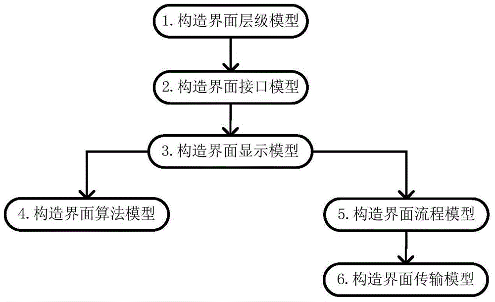
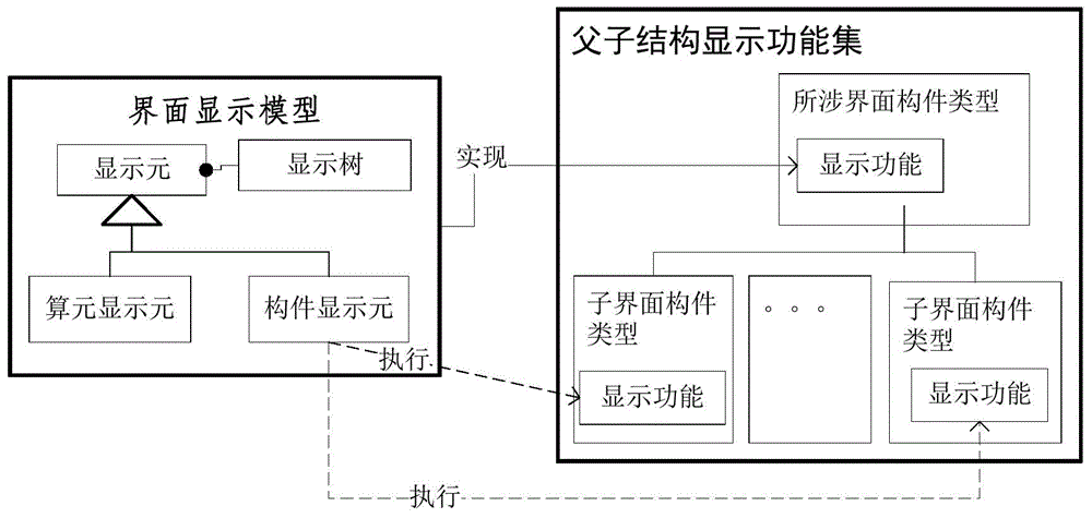
The invention discloses a universal interface modeling method for constructing an interface model based on an interface element model. The interface model is constructed by taking an interface hierarchy model, an interface model, an interface display model, an interface algorithm model, an interface flow model and an interface transmission model as step elements after basic elements of the interface element model are determined; visual system modeling specifications with the advantages of computability, universality and usability are provided for various fields, wherein the system model constructed with the method is clear in structure, adjustable in layer and controllable in modeling particle size, and has full consistency of being computable; methods are unified, thereby facilitating the top-down analysis design and the bottom-up integration realization and being suitable for modeling of various interface systems; and few modeling elements are used and the modeling method is simple, so that personnel in common fields can construct the system model independently and easily even if the personnel do not understand a modeling language and a computer program language, the dependence and communication on professional modeling personnel or program development personnel are eliminated, and the modeling time is greatly shortened.

Description

technical field [0001] The invention relates to the technical field of software engineering, in particular to a general interface modeling method and a computer program product for constructing an interface model based on an interface element model. Background technique [0002] The interface determines the success of a software to a large extent. The key reasons are: first, the interface is the concrete embodiment of the business, and second, the interface directly determines the user experience. Because of the prominent position of the interface, interface development is almost destined to become the focus of software development, especially the development of complex software systems. [0003] The software interface shows three characteristics: (1) diversity: the software is used in various fields, and the development theme of the software interface covers almost all application fields; (3) Complexity: Interface development occupies a considerable proportion of workload ...

Claims


Application Information

Patent Timeline
Patent Type & Authority Applications(China)
IPC IPC(8): G06F9/44
CPCG06F9/44
Inventor 符长明龙春生唐鸿
Owner CHENGDU PUZHONG SOFTWARE CO LTD
Learn More