
Gear Fan Chengyi

A transmission gear and rack technology, applied in the field of teaching auxiliary equipment, can solve the problems of low stability, long time consumption, large manual operation error, etc., and achieve the effect of improving demonstration efficiency and reducing experiment time.

Active Publication Date: 2018-06-29
GUILIN UNIVERSITY OF TECHNOLOGY
View PDF5 Cites 0 Cited by
  • Summary
  • Abstract
  • Description
  • Claims
  • Application Information

AI Technical Summary

Problems solved by technology

[0002] At present, the gear fan used in the auxiliary teaching laboratory is generally mechanical. When using it, it is necessary to manually move the slide plate to draw the tooth profile to form the required tooth profile. Therefore, in the process of experimenting, it is necessary to reciprocate Moving the slider multiple times will easily cause the moving distance to be too large or too small during the moving process and requires multiple adjustments to achieve the required moving distance, so the efficiency is low and it takes a lot of time, and the error of manual operation is large and the stability is not stable. High, so that the drawn tooth profile is not clear, which affects the observation of the students on the machining process of the gear model

Method used


Image

  • Gear Fan Chengyi
  • Gear Fan Chengyi
  • Gear Fan Chengyi

Examples


Embodiment Construction

[0015] In order to understand the above-mentioned purpose, features and advantages of the present invention more clearly, the present invention will be further described in detail below in conjunction with the accompanying drawings and specific embodiments. It should be noted that, in the case of no conflict, the embodiments of the present application and the features in the embodiments can be combined with each other.

[0016] In the following description, many specific details are set forth in order to fully understand the present invention. However, the present invention can also be implemented in other ways than described here. Therefore, the protection scope of the present invention is not limited by the specific implementation disclosed below. Example limitations.

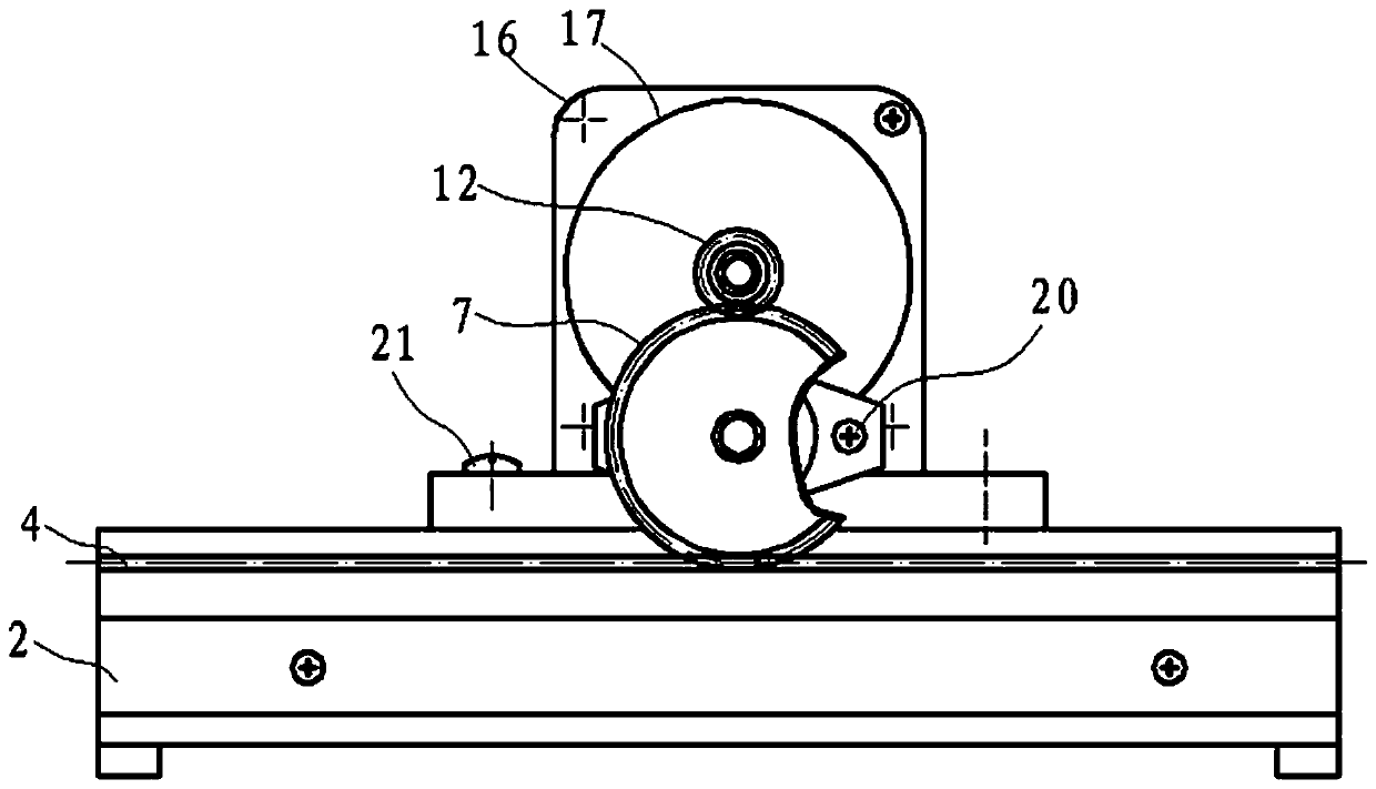
[0017] Such as figure 1 , 2 As shown, it includes a base plate 18, a control circuit module (not shown in the figure), a drive motor 17, a transmission gear 12, a reduction gear 7, a rack 4, a slider 22 and...


PUM


Abstract

The invention provides a gear fan forming instrument. The gear fan forming instrument includes a base plate, a control control circuit module, a driving motor, a transmission gear, a reduction gear, a rack, a slider and a bearing. The base plate is provided with a guide rail groove. , the slider is provided with a guide rail, the guide rail is matched and connected to the guide rail groove, the rack is fixedly connected with the slider, the motor is fixed on the bottom plate of the base, the control module and the The drive motor is connected, the reduction gear is fixed on the bottom plate of the base through the bearing and meshed with the transmission gear and the rack at the same time, and the transmission gear is fixed on the motor shaft of the drive motor , the gear fan provided by the present invention can realize the control of the sliding distance of the slider, so that each time the moving distance is equal, there is no need to reciprocate the moving distance, the drawn tooth profile is clear and distinct, and the electronically controlled automatic transmission is realized. , improving the drawing efficiency.

Description

technical field [0001] The invention relates to the field of teaching auxiliary equipment, in particular to a gear fan forming instrument. Background technique [0002] At present, the gear fan used in the auxiliary teaching laboratory is generally mechanical. When using it, it is necessary to manually move the slide plate to draw the tooth profile to form the required tooth profile. Therefore, in the process of experimenting, it is necessary to reciprocate Moving the slider multiple times will easily cause the moving distance to be too large or too small during the moving process and requires multiple adjustments to achieve the required moving distance, so the efficiency is low and it takes a lot of time, and the error of manual operation is large and the stability is not stable. High, so that the drawn tooth profile is not clear, which affects the observation of the students on the machining process of the gear fan. Contents of the invention [0003] The present inventi...

Claims


Application Information

Patent Timeline
Patent Type & Authority Patents(China)
IPC IPC(8): G09B25/02
Inventor 严天祥韦健毫黄华东陆金朗陆世博黎乾君黄灿华
Owner GUILIN UNIVERSITY OF TECHNOLOGY
Learn More