Method for self-calibrating a rotary encoder

A rotary encoder and self-calibration technology, which is applied in the direction of converting sensor output, instruments, and using electric/magnetic devices to transfer sensing components, etc., can solve the problems of increasing calibration effort and time, reduce cost and complexity, and eliminate centrifugal effect of error

Active Publication Date: 2016-01-06
MITSUBISHI ELECTRIC CORP
View PDF9 Cites 5 Cited by
  • Summary
  • Abstract
  • Description
  • Claims
  • Application Information

AI Technical Summary

Problems solved by technology

Such requirements increase the effort and time of calibration

Method used


Image

  • Method for self-calibrating a rotary encoder
  • Method for self-calibrating a rotary encoder
  • Method for self-calibrating a rotary encoder

Examples


Embodiment Construction

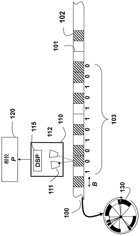
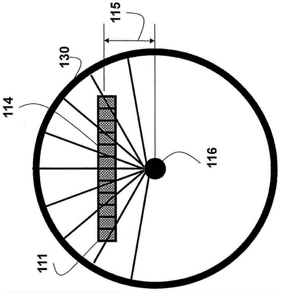
[0028] Embodiments of the present invention provide a monorail absolute rotary encoder. The read head can be a linear charge coupled device (CCD) or complementary metal oxide semiconductor (CMOS) to obtain a 1D image of the rotating circular scale. The 1D image comprises a linear array of pixels. The scale comprises reflective and non-reflective areas arranged according to the deBruijn sequence. The deBruijn sequence is a good fit because the pattern itself is circular in nature.

[0029] Absolute Round Dial

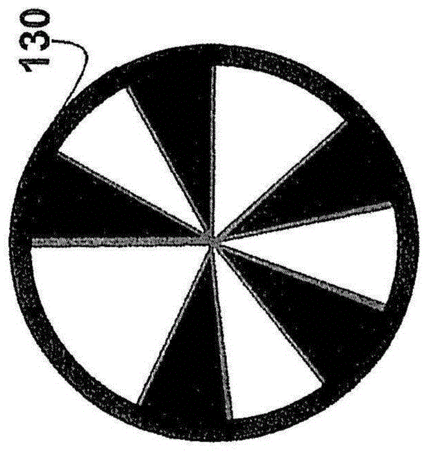
[0030] Figure 1 shows a small part of a circular scale 100 of an absolute encoder of an embodiment of our invention. Details of the dial are described in US application 13 / 100092. This dial is used to determine the high resolution phase P120.

[0031] The dial may include alternating light reflective 101 and non-reflective 102 marks or digits. The markings may also alternate between opaque and transparent depending on the relative position of the light source with ...


PUM


Abstract

A method for self-calibrating a rotary encoder including a single read-head (111) and a circular scale (101), comprises the steps of: acquiring calibration samples (150) by the read-head for rotational angles (Theta) of the circular scale; and estimating spatial frequency (F) and spatial distortion parameters (Alpha, Beta) of the encoder from the calibration samples for self-calibrating the rotary encoder.

Description

technical field [0001] The present invention relates to measuring devices, and in particular to absolute rotary encoders for measuring absolute angles of rotation. Background technique [0002] Accurate estimation of linear position and rotational angle is an important task in industrial automation and similar applications. Devices such as numerically controlled (CNC) machines, drills, robotic arms or laser cutters, and assembly lines all require precise measurements. Feedback control is often used for precise measurements. [0003] A typical encoder consists of a dial and a read head. Optical encoders are commonly used to measure absolute or relative linear position or rotational angle. Relative encoders measure relative position or angle over a dial cycle and need to count the number of dial cycles experienced to determine the absolute position or angle. Absolute encoders do not require memory or power to store the current position or angle, and these can be retrieved ...

Claims


Application Information

Patent Timeline
Patent Type & Authority Applications(China)
IPC IPC(8): G01D5/244G01D5/347
CPCG01D5/34715G01D18/001
Inventor A·阿格拉瓦尔J·桑顿
Owner MITSUBISHI ELECTRIC CORP
Why Eureka
Try Eureka