Sedimentation device for sewage treatment

A settling device and sewage treatment technology, which is applied in the direction of the feeding/discharging device of the settling tank, settling tank, etc., can solve the problems of large kinetic energy of suspended particles, long standing time, and high production cost, so as to reduce production cost and increase production cost. Large attachment area, effect of reducing tailings

Inactive Publication Date: 2016-01-13
广西大美节能设备有限公司
View PDF6 Cites 5 Cited by
  • Summary
  • Abstract
  • Description
  • Claims
  • Application Information

AI Technical Summary

Problems solved by technology

[0002] Sewage contains a large number of suspended particles, which are usually treated by sedimentation. The suspended particles move downward under the action of gravity, so as to realize the separation of particles. In the prior art, the Chinese patent No. CN104383723A discloses a The sewage treatment device includes a tank body with an open upper end and a diversion cylinder extending into the tank from the open end. The outer wall of the body is sealed and connected, and the edge of the small end of the cone extends downward to the lower part of the tank to form a tubular part. A conduit extending out of the tank is provided at the bottom of the tank and directly below the tubular part. The upper end of the conduit Higher than the inner bottom surface of the tank body, the upper wall of the tank body is provided with a drain pipe, and the bottom of the tank body is provided with a drain valve. When using this invention, due to the fast flow of sewage in the tank body, the Suspended particles have high kinetic energy, so the standing time is long. If the time needs to be shortened, a large amount of chemicals must be added to the sewage, and the production cost is high. This invention does not propose a solution for this

Method used


Image

  • Sedimentation device for sewage treatment

Examples


Embodiment Construction

[0014] The technical solution of the present invention will be further described below in conjunction with the accompanying drawings, but the scope of protection is not limited to the description.

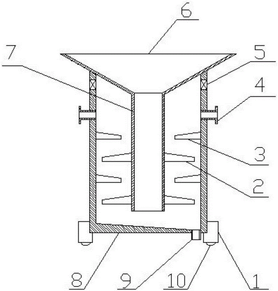
[0015] Such as figure 1 The shown settling device for sewage treatment includes a support base 1, a settling chamber 8, a feed pipe 7, a feed hopper 6 and a discharge pipe 4, and the settling chamber 8 is installed on the support base 1, so The settling chamber 8 is a cylindrical cavity structure with the bottom inclined towards the sewage outlet. The inner wall of the settling chamber 8 is obliquely equipped with a deflector A3, and a deflector B2 is arranged between the deflectors A3. The deflector B2 is obliquely installed on the feed pipe 7, and the feed pipe 7 is installed on the feed hopper 6, and the feed hopper 6 is installed on the upper edge of the settling chamber 8, and the discharge pipe 4 Installed below the upper edge of the settling chamber 8 , the settling chamber...


PUM


Abstract

The invention discloses a sedimentation device for sewage treatment. The sedimentation device includes a supporting pedestal, a sedimentation chamber, a material guiding pipe, a feeding hopper and discharge pipes; the sedimentation chamber is mounted on the supporting pedestal and has a cylindrical cavity body structure having the bottom tilted to a sewage draining port; the inner wall of the sedimentation chamber is provided with guide plates A in an tilting manner; guide plates B are arranged between the guide plates A and are mounted on the material guiding pipe in an tilting manner; the material guiding pipe is mounted on the feeding hopper; the feeding hopper is mounted at the upper edge opening of the sedimentation chamber; the discharging pipes are mounted below the upper edge opening of the sedimentation chamber; the sedimentation chamber is provided with exhaust ports; the exhaust ports are located above the discharging pipes. A tank body and the material guiding pipe are adopted, and the guide plates A and the guide plates B are respectively mounted on the tank body and the material guiding pipe in the titling manner, so that the sewage flow rate is reduced, the particle adhesion area is increased, the sedimentation time and the drug use amount are reduced, the production cost is lowered, and the production efficiency is improved.

Description

technical field [0001] The invention relates to the technical field of environmental protection equipment manufacturing, in particular to a settling device for sewage treatment. Background technique [0002] Sewage contains a large number of suspended particles, which are usually treated by sedimentation. The suspended particles move downward under the action of gravity, so as to realize the separation of particles. In the prior art, the Chinese patent No. CN104383723A discloses a The sewage treatment device includes a tank body with an open upper end and a diversion cylinder extending into the tank from the open end. The outer wall of the body is sealed and connected, and the edge of the small end of the cone extends downward to the lower part of the tank to form a tubular part. A conduit extending out of the tank is provided at the bottom of the tank and directly below the tubular part. The upper end of the conduit Higher than the inner bottom surface of the tank body, th...

Claims


Application Information

Patent Timeline
Patent Type & Authority Applications(China)
IPC IPC(8): B01D21/02B01D21/24
Inventor 严燕华
Owner 广西大美节能设备有限公司
Why Eureka
Try Eureka