Self-cleaning filter for drop irrigation water

A technology for cleaning filters and water filters, applied in fixed filter element filters, filter circuits, filter separation and other directions, it can solve the problems of poor filtering effect, inconvenient filtering and cleaning, clogging of drip irrigation pipes, etc., so as to achieve convenient use and maintenance. , convenient operation, reasonable structure effect

Inactive Publication Date: 2016-01-13
新疆石大国利农业科技股份有限公司
View PDF6 Cites 1 Cited by
  • Summary
  • Abstract
  • Description
  • Claims
  • Application Information

AI Technical Summary

Problems solved by technology

[0006] The purpose of the present invention is to provide an economical and practical drip irrigation water with reasonable structure, easy to automatically realize self-cleaning, easy to operate, effectively solve the technical problems of poor filtering effect of the existing drip irrigation system, inconvenient filtering and cleaning, and easy to cause blockage of the drip irrigation pipeline. self-cleaning filter

Method used


Image

  • Self-cleaning filter for drop irrigation water
  • Self-cleaning filter for drop irrigation water
  • Self-cleaning filter for drop irrigation water

Examples


Embodiment 1

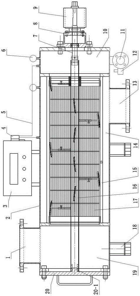
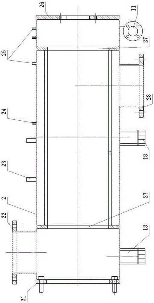
[0036] refer to figure 1 — Figure 9 , a self-cleaning filter for drip irrigation in the present invention, comprising a tank body 2, which is provided with a water inlet 1, a water outlet 13, and a sewage outlet 11, and one end of the tank body 2 is provided with an end cover 20, and the other side A sealing cover 8 is provided, a cylindrical filter screen 17 is arranged axially in the tank body 2, a cleaner 16 is arranged in the filter screen 17, a controller 3 and a cleaning motor 9 are arranged outside the tank body 2; the controller 3 is Box-type liquid crystal display multi-axis controller, the starting mode is partial pressure difference self-cleaning start. The tank body 2 is horizontal and horizontal, the water inlet 1 is located above the tank body 2 , the water outlet 13 is located below the tank body 2 , and the tank body 2 is provided with a support 18 .

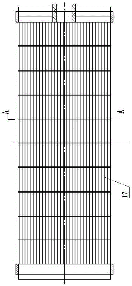
[0037]The filter screen 17 is fixed in the tank body 2 by the filter screen support 15 and the filter scree...

Embodiment 2

[0044] Compared with Embodiment 1, the difference lies in that the cleaning brushes 32 are arranged around the central rotating shaft 33 in a helical manner.

Embodiment 3

[0046] Compared with Embodiment 1, the difference lies in that the filter screen 17 is a steel wire mesh, and the cross section of the steel wire 29 used is wedge-shaped. When the steel wire 29 is installed, the wedge-shaped big end 30 faces inward and the small end 31 faces outward.

[0047] Example 3:

[0048] Compared with Embodiment 1, the difference lies in that the controller 3 is a box-type liquid crystal display multi-axis controller, and the starting mode is self-cleaning start-up with fixed time or manual cleaning start-up mode.


PUM


Abstract

The present invention relates to an agricultural drip irrigation technology, in particular to a filter for performing effective filtration on agricultural drip irrigation water and achieving self cleaning in a drip irrigation system. A self-cleaning filter for drop irrigation water comprises a tank body which is provided with a water inlet, a water outlet and a drain outlet; an end cap is arranged at one end of the tank body while a sealing cover is arranged on the other side; the tank body is axially provided with a cylinder filter screen, the filter screen is internally provided with a cleaner, and a controller and a cleaning motor are arranged on the outside of the can. The structure of the cleaner comprises a center rotation shaft, wherein the center rotation shaft is a hollow shaft; a plurality of cleaning brushes are arranged on the hollow shaft at intervals; and the inner part of the tank body is divided into a source water chamber, a water cleaning chamber and a sewage draining chamber through a filter screen support flange and the filter screen. The filter provided by the present invention is reasonable in structure and relatively high in automation degree, can automatically achieve self cleaning, and is convenient to filter and clean. In a cleaning process, water supply will not be affected by cleaning cutout. Therefore, the filter provided by the present invention is an economical and practical self-cleaning filter for drop irrigation water.

Description

technical field [0001] The invention relates to agricultural drip irrigation technology, in particular to a filter used in a drip irrigation system to effectively filter agricultural drip irrigation water and realize self-cleaning. Background technique [0002] Drip irrigation uses plastic pipes to send water to the roots of crops through holes or drippers on capillaries with a diameter of about 10mm for local irrigation. It is currently the most effective water-saving irrigation method in arid and water-scarce areas, with a water utilization rate of up to 95%. Compared with sprinkler irrigation, drip irrigation has a higher effect of saving water and increasing production. At the same time, it can be combined with fertilization to more than double the fertilizer efficiency. It is suitable for irrigation of fruit trees, vegetables, commercial crops and greenhouses, and can also be used for irrigation of field crops in places where there is drought and water shortage. The d...

Claims


Application Information

Patent Timeline
Patent Type & Authority Applications(China)
IPC IPC(8): B01D36/04B01D35/02B01D29/01B01D29/64A01G25/02
Inventor 冯明昌王孔相郑重李建强
Owner 新疆石大国利农业科技股份有限公司
Why Eureka
Try Eureka