Dry powder feeding device

A feeding device and dry powder technology, applied in the field of building materials, can solve the problems of uneven mixing, inability to remove metal impurities, inability to mix dry powder materials evenly, etc., and achieve the effect of facilitating popularization and simple operation.

Active Publication Date: 2016-01-13
来凤县宇翔钙业有限公司
View PDF6 Cites 8 Cited by
  • Summary
  • Abstract
  • Description
  • Claims
  • Application Information

AI Technical Summary

Problems solved by technology

[0003] In the production and transportation of dry powder, a large number of metal objects need to be contacted, and some metal parts such as nails, metal chips, etc. will enter it. These metal impurities can easily damage the mixing page of the mixer after entering the mixer and other equipment, resulting in loss, and the existing mixing system cannot mix the dry powder materials well, resulting in poor quality of the final building material coating, especially when the dry powder is wet and agglomerated, it is more prone to uneven mixing, and at the same time it cannot be mixed Metal impurities in dry powder are removed, so there is an urgent need for a feeding device that can remove metal impurities and mix dry powder evenly during the feeding process of machinery and equipment

Method used


Image

  • Dry powder feeding device
  • Dry powder feeding device
  • Dry powder feeding device

Examples


Embodiment 1

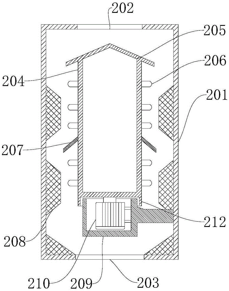
[0043] Such as Figure 1 to Figure 2 As shown, the present embodiment provides a dry powder feeding device, including a housing 201, a stirring roller 204, a magnetic member and a motor fixing seat 209, and the upper and lower ends of the housing 201 are respectively provided with a feed port 202 and a discharge port. The port 203 and the shell 201 are made of metal material, and the whole shell 201 is cylindrical. The feed port 202 and the discharge port 203 are respectively arranged in the middle of the upper and lower ends of the shell 201 .

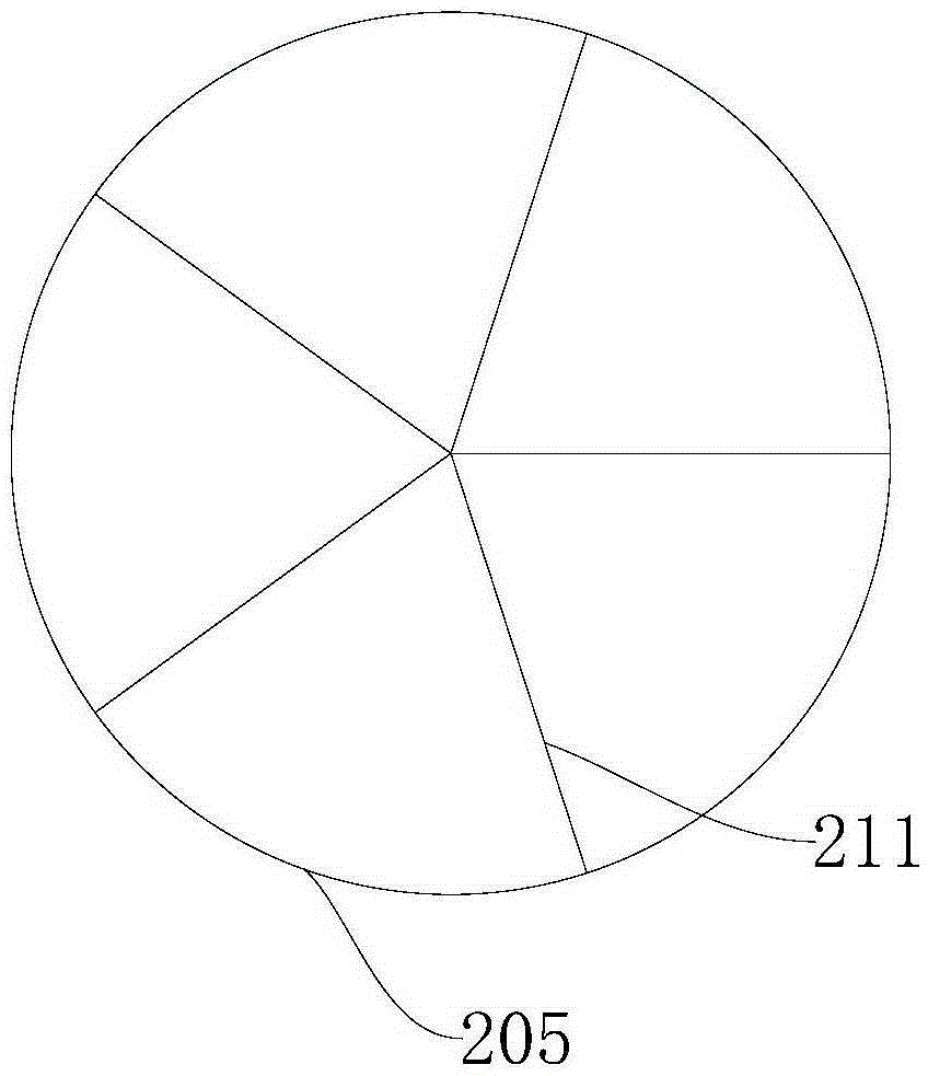
[0044] The stirring roller 204 is vertically arranged in the middle of the housing 201 and is located in the housing 201. The upper end of the stirring roller 204 is provided with a conical cap 205, and the conical cap 205 and the stirring roller 204 are integrally formed. Yes, the brim of the conical cap 205 protrudes from the outer wall of the stirring roller 204 to form a bamboo hat, and the conical cap 205 covers the stirring roll...

Embodiment 2

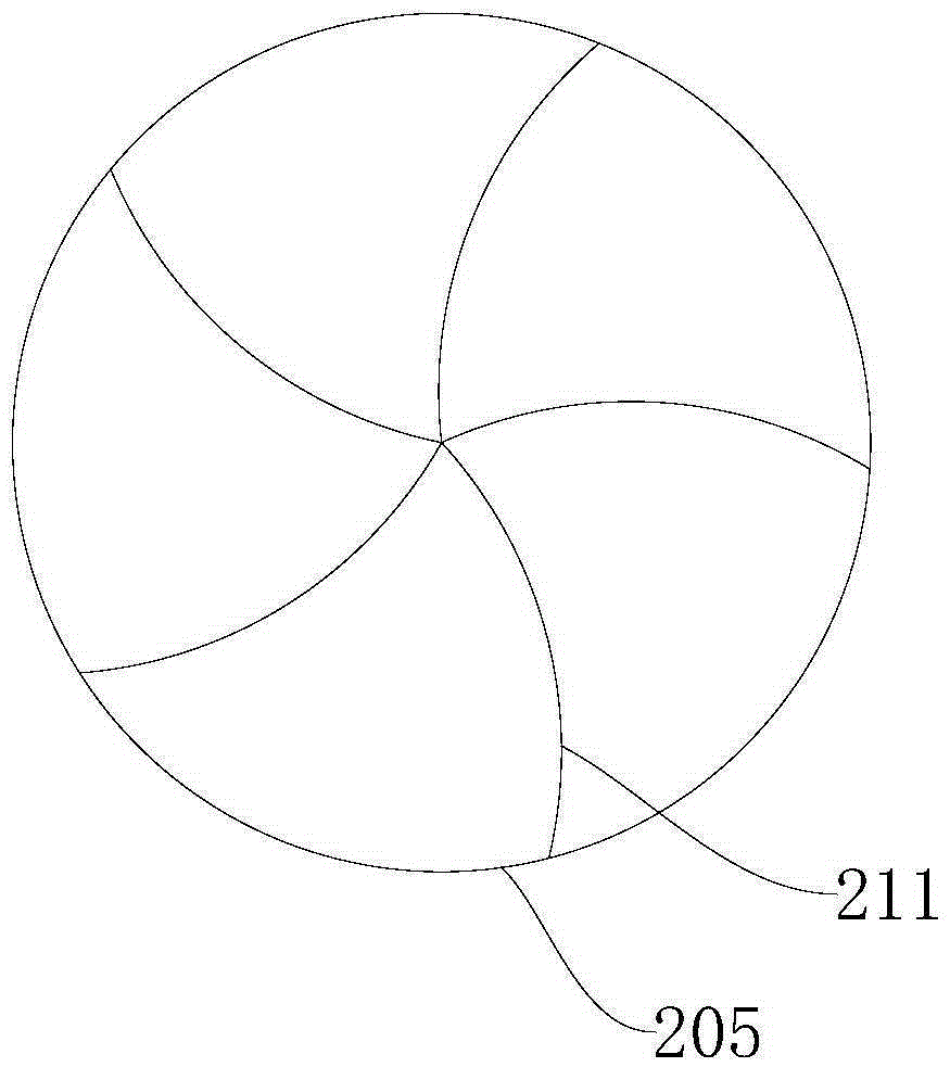
[0061] Embodiment 2, refer to image 3

[0062] The basic structure, principle and technical effect of the dry powder feeding device provided in this example are the same as those in Example 1. For a brief description, for parts not mentioned in this example, refer to the corresponding content in Example 1.

[0063] The difference between this embodiment and Embodiment 1 is that, in this embodiment, the rib 211 on the conical cap 205 is arc-shaped, such as image 3 As shown, there are five ribs 211, and the ribs 211 are drawn from the apex of the conical cap 205 to the brim of the conical cap 205. The advantage of this arc-shaped rib 211 is that the length of the rib 211 is longer than that of a straight line. The convex rib 211 is longer, and the contact area between the conical cap 205 and the dry powder is larger during the rotation process of the conical cap 205, and the pulverizing and mixing effect on the dry powder is better.

[0064] The dry powder feeding device pro...


PUM


Abstract

The invention provides a dry powder feeding device, and belongs to the field of construction and building materials. The dry powder feeding device comprises a housing, a stirring roller and a magnetic part, wherein the upper and lower ends of the housing are respectively provided with a feeding hole and a discharge hole; the stirring roller is vertically arranged in the middle of the housing; the upper end of the stirring roller is provided with a tapered cap; the lower end of the stirring roller is connected with a motor for driving the stirring roller to rotate; the motor is fixed on the inner wall of the housing; the magnetic part is arranged on the inner wall of the housing; the cap edge of the tapered cap extends out of the outer wall of the stirring roller; and a channel for allowing dry powder to pass through is formed between the magnetic part and the stirring roller. According to the dry powder feeding device provided by the invention, the rotary stirring roller is arranged, so that the dry powder while entering is thrown to the magnetic part on the housing by virtue of the tapered cap on the stirring roller, and therefore, dry powder blocks can be scattered, metal impurities mixed in the dry powder also can be adsorbed, and the metal impurities are prevented from damaging machine equipment; and the dry powder feeding device is simple to operate and beneficial for popularization.

Description

technical field [0001] The invention relates to the field of building materials, in particular to a dry powder feeding device. Background technique [0002] In the process of making building materials and coatings, various dry powder materials need to be used. These dry powder materials are stored in different storage bins due to different materials, and these different dry powder materials need to be mixed in the subsequent processing process. [0003] In the production and transportation of dry powder, a large number of metal objects need to be contacted, and some metal parts such as nails, metal chips, etc. will enter it. These metal impurities can easily damage the mixing page of the mixer after entering the mixer and other equipment, resulting in loss, and the existing mixing system cannot mix the dry powder materials well, resulting in poor quality of the final building material coating, especially when the dry powder is damp and agglomerated, it is more likely to be u...

Claims


Application Information

Patent Timeline
Patent Type & Authority Applications(China)
IPC IPC(8): B03C1/02B01F7/16B02C19/00
Inventor 关雪松张占华辛超
Owner 来凤县宇翔钙业有限公司
Why Eureka
Try Eureka