Two-degree-of-freedom workpiece clamping mechanism

A technology of degrees of freedom and workpieces, applied in the direction of manufacturing tools, metal processing equipment, forging/pressing/hammering machinery, etc., can solve problems such as change uncertainty and difficulty in identification

Inactive Publication Date: 2016-01-13
WUXI QINGYANG MACHINERY MFG
View PDF6 Cites 0 Cited by
  • Summary
  • Abstract
  • Description
  • Claims
  • Application Information

AI Technical Summary

Problems solved by technology

Uncertainty in the environment manifests itself as uncertainty of change and difficulty in discerning

Method used


Image

  • Two-degree-of-freedom workpiece clamping mechanism

Examples


Embodiment 1

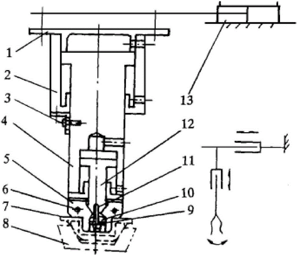
[0018] attached by figure 1As shown, the telescopic pneumatic cylinder 2 is connected to the beam through the bolt 1, the pneumatic cylinder 4 is also the piston rod of the telescopic pneumatic cylinder 2, and the L-shaped plate 3 is fixed on the pneumatic cylinder 4 by bolts to limit the stroke of the pneumatic cylinder 4. When the pneumatic cylinder 4 rose to the highest position, the L-shaped plate leaned against the telescopic pneumatic cylinder 2. The clamping claw 5 is connected to the frame through a cylindrical pin 6. Note that the contact surface between the clamping claw 5 and the air pressure piston rod 12 is designed as an inclined surface. When the air pressure piston rod 12 is extended, the two clamping claws are opened to clamp Item 7. The beam on the telescopic pneumatic cylinder 2 links to each other with the piston column of the hydraulic telescopic cylinder 13, and the left-right direction stroke of the hydraulic telescopic cylinder 13 controls the mechanis...


PUM


Abstract

The invention discloses a two-degree-of-freedom workpiece clamping mechanism. A telescopic pneumatic cylinder is connected onto a cross beam through a bolt; a pneumatic cylinder is a piston rod of the telescopic pneumatic cylinder; and an L-shaped plate is fixed on the pneumatic cylinder through a bolt and used for limiting the stroke of the pneumatic cylinder, and when the pneumatic cylinder rises to a highest position, the L-shaped plate leans against the telescopic pneumatic cylinder. Clamping claws are connected onto a rack through straight pins, a contact surface of each clamping claw and a pneumatic piston cylinder is designed to be an inclined plane, and when the pneumatic piston cylinder extends, the two clamping claws are opened to clamp an object. The cross beam on the telescopic pneumatic cylinder is connected with the piston cylinder of the telescopic pneumatic cylinder, and the telescopic pneumatic cylinder controls the horizontal stroke of the mechanism. The two-degree-of-freedom workpiece clamping mechanism disclosed by the invention has the benefits as follows: a forge piece can be quickly taken out from die forging, the production efficiency is improved, the processing flow is standardized, meanwhile, multiple workpiece clamping mechanisms can be arranged at the same time and the forge piece quality is improved.

Description

technical field [0001] The invention relates to the field of industrial production line equipment and machinery manufacturing, in particular to a two-degree-of-freedom clamping workpiece mechanism. Background technique [0002] The machinery manufacturing industry occupies an important position in the national economy. It directly affects the development of many industries, such as: aerospace industry, military industry, transportation and other industries that are closely related to the lifeline of the national economy. At present, the mechanical processing in my country is mainly based on traditional processing methods, and most enterprises are still in stand-alone automation. automation stage. The processing efficiency is low, the processing accuracy is low, the processing quality is poor, and the processing stability is not good. However, foreign advanced manufacturing enterprises have basically eliminated traditional machinery, and adopted equipment with full automatio...

Claims


Application Information

Patent Timeline
IPC IPC(8): B21J13/10
CPCB21J13/10
Inventor 唐靖岚
Owner WUXI QINGYANG MACHINERY MFG
Why Eureka
Try Eureka