Device for manufacturing large-size U-shaped part

A large-size, U-shaped technology, applied in the field of non-planar thermosetting composite material molding, can solve the problem of unsatisfactory shear strength, etc., and achieve the effect of stable and uniform product size and consistent appearance and color

Inactive Publication Date: 2016-01-13
ZHUZHOU TIMES NEW MATERIALS TECH
4 Cites 4 Cited by

AI-Extracted Technical Summary

Problems solved by technology

[0003] The traditional method of forming large-sized U-shaped structural parts is pultrusion molding. The advantage of pultrusion molding method is that it can be produced continuously, but there are other problems: because pultrusion molding uses gla...

Method used

As another embodiment of the present invention, there is glue flow groove 8 at the edge position that described slide type module 3 contacts with upper mold 1 bottom, in pressing process, is used for unnecessary glue liquid to flow out smoothly, in order to prevent cloggi...

Abstract

The invention discloses a device for manufacturing a large-size U-shaped part. As a hot pressing forming process is adopted, tension of the large-size U-shaped part in a traditional pultrusion process is avoided, and the parallel layer direction shearing strength of the large-size U-shaped part meets the requirement. As a sliding block spliced structure is adopted, the top, the left side and the right side of the large-size U-shaped part are stressed simultaneously during the mould pressing forming process; the stress on all the surfaces is gradually increased, so that the forming process requirements of thermosetting compound materials are met. Meanwhile, automatic demoulding of products is achieved, and the obtained products are stable and uniform in size and consistent in appearance color.

Technology Topic

PultrusionEngineering +6

Image

  • Device for manufacturing large-size U-shaped part
  • Device for manufacturing large-size U-shaped part
  • Device for manufacturing large-size U-shaped part

Examples

  • Experimental program(1)

Example Embodiment

[0019] In order to make the objectives, technical solutions, and advantages of the present invention clearer, the following further describes the present invention in detail with reference to specific embodiments and drawings.
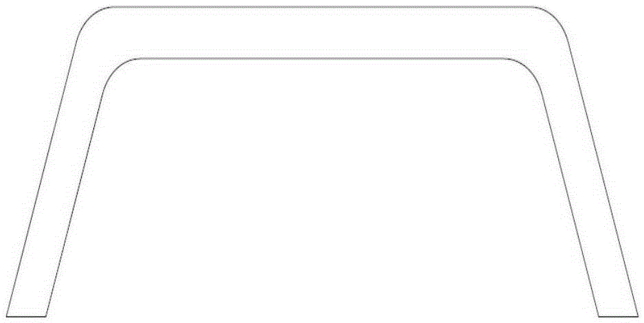
[0020] Such as figure 1 Shown is a schematic cross-sectional view of a trapezoidal large U-shaped piece. The trapezoidal large-size U-shaped piece is a groove-like structure with a U-shaped cross-section, the cross-section of the large-size U-shaped groove is an isosceles trapezoid, and the width of the opening of the large-size U-shaped piece is larger than that of the bottom. The width of the side. In actual production, the structure of the mold can be changed according to requirements, and then the shape of the large-size U-shaped piece can be changed.
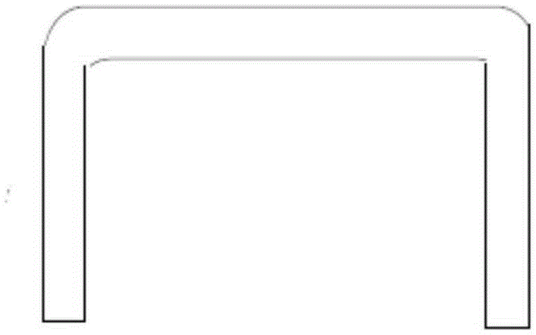
[0021] Such as figure 2 Shown is a schematic cross-sectional view of a large rectangular U-shaped piece. The rectangular large-size U-shaped piece is a groove-like structure with a U-shaped cross section, the cross-section of the large-size U-shaped groove is rectangular, and the width of the opening of the large U-shaped piece is equal to that of the bottom side. width. In the actual production, the structure of the mold can be changed according to the demand, and then the shape of the large-size U-shaped part can be changed.
[0022] Such as image 3 Shown is a schematic cross-sectional view of an embodiment of a device for manufacturing a large-size U-shaped piece. The apparatus for manufacturing a large-size U-shaped piece includes an upper mold 1 and a lower mold 2. The upper mold 1 is a U-shaped groove structure in cross section, and the lower mold 2 includes two L-shaped slides in cross section. Type module 3, a fixed module 4 with an isosceles trapezoid in cross-section, and a base 5; the fixed module 4 is fixed on the base 5, and the two sliding modules 3 are respectively located on the fixed module 4 On both sides, the upper mold 1 is inverted on the top ends of the two sliding modules 3.
[0023] Further, a spring 6 is provided between the base 5 and the sliding module 3, and the springs 6 are symmetrically and evenly distributed on both sides of the fixed module 4. The bottom end of the spring 6 is connected to the base 5 The upper surface of the spring 6 is fixedly connected, and the top end of the spring 6 is fixedly connected to the bottom surface of the sliding module 3. The spring 6 is a high-strength spring. In an embodiment of the present invention, the springs 6 are in three groups, two in each group.
[0024] As an embodiment of the present invention, the upper mold 1 has heat conduction oil channels 7 distributed along the length direction and/or the base has heat conduction oil channels 7 distributed along the length direction and/or the fixed module There are heat conducting oil channels 7 distributed along the length. The heat-conducting oil channel 7 is used for passing heat-conducting oil to heat the entire mold.
[0025] As an embodiment of the present invention, the number of heat-conducting oil channels 7 in the upper mold 1 is 8, the number of heat-conducting oil channels 7 in the fixed module 4 is one, and the heat-conducting oil channels 7 in the base 5 are 2 pcs. During the pressing process, you can choose to open or close the heat-conducting oil channels 7 according to the actual heating needs, and the temperature in the mold can be changed by controlling the number of heat-conducting oil channels 7 through which the oil passes, thereby controlling the temperature during hot pressing. In actual production, the number of heat transfer oil channels can be changed according to heating requirements.
[0026] As another embodiment of the present invention, the edge position of the sliding module 3 that contacts the bottom of the upper mold 1 is provided with a glue flow groove 8, which is used for smooth flow of excess glue during the pressing process to prevent blockage and affect heat The exhaust process in the pressure process. If the hot air cannot be smoothly discharged during the hot pressing process, it will affect the stable and uniform size of the U-shaped structure molded part, and the uniform appearance and color.
[0027] As another embodiment of the present invention, the cross-section of the fixed module 4 is an isosceles trapezoid with a narrow top and a wide bottom. Since the left and right sides of the isosceles trapezoid are symmetrical, the two sides of the fixed module 4 have the same length. During the hot pressing process and the demolding process, the two sliding modules 3 can be synchronized upward or downward. Move, so that the left and right sides of the large U-shaped piece produced are consistent in shape. Since the fixed module 4 is symmetrical on the left and right sides, the structure of the sliding module 3 is the same. The structure of the large U-shaped piece produced is It is also consistent with the strength, and further realizes the stable and uniform size of the U-shaped structure molded part, and the uniform appearance and color. During the hot pressing process, the upper mold 1 does not move, and the lower mold 2 moves upward. In the process of moving, the pressure on the glass cloth gradually increases, and pressure is applied to all parts of the glass cloth at the same time; because the two sides of the glass cloth are simultaneously stressed with the top, and the force on both sides of the glass cloth is uniform, the large size U is obtained. The density and mechanical properties of the top and sides of the shaped part are the same.
[0028] Such as Figure 4 Shown is a schematic diagram of the working principle of an embodiment of the present invention; stacking several sheets of glued grey cloth 9 and spreading a release film on the grey cloth 9 or applying a release agent on the mold, and then The rubberized grey cloth 9 is placed on the lower mold 2. When the press is turned on, the oil cylinder pushes the lower mold 2 to rise. During the ascending process, when the lower mold 2 rises to the bottom surface of the upper mold 1, when there is pressure at the beginning, the top of the lower mold 2 starts to be stressed, and the sliding type The module 3 slides down accordingly. During the process, the upper and lower molds 1 and 2 gradually close, and the upper and lower molds 1 and 2 are gradually closed. At the same time, due to the downward movement of the sliding module 3, the lateral width of the lower mold 2 gradually increases. , Provides pressure on both sides of the glued grey fabric 9, and the pressure gradually increases, as shown Figure 4 Shown. Subsequently, the temperature of the mold is raised, the glued grey fabric 9 is pre-cured to a certain extent, and then hot-pressed and molded according to the molding process, and finally cooled and demolded. Through this design and pressing method, the pressure on both sides of the U-shaped structure can be increased with the increase of the top pressure, which can meet the process requirements of the pressure of each structure surface during the molding process of thermosetting composites, and ensure the molding of the entire U-shaped structure. During the process, the force on the top and both sides is even.
[0029] The pressing process of the manufacturing method is determined by the curing characteristics of the resin used in the hot pressing process. The pre-pressing stage is the pre-pressing stage. The pressure in this stage is relatively small. When the resin system is cured to a certain degree, the fluidity of the resin will decrease, and the temperature will be increased and the pressure will be increased to make the product cured completely.
[0030] Figure 5 Shown is a schematic diagram of temperature and pressure changes over time in processing a U-shaped piece using epoxy glass grey cloth in an embodiment of the present invention. According to the curing characteristics of the epoxy resin, 5 oil passages are used for heating. The specific preparation process is as follows:
[0031] Cut the prepared epoxy glass grey cloth to a certain specification, then stack the cut grey cloth, lay the film on top and bottom, place the lower mold, turn on the press, the lower mold rises, rise to a certain stroke and then heat it according to the forming process Compression molding. The molding process is Figure 5 Shows the law of temperature and pressure changes over time.
[0032] Image 6 It is a schematic diagram of temperature and pressure changes with time in processing a U-shaped piece with epoxy phenolic glass cloth in an embodiment of the present invention. According to the curing characteristics of the epoxy phenolic resin, the method of heating with 7 oil passages is adopted. The specific preparation process is as follows:
[0033] Cut the prepared epoxy phenolic glass grey cloth to a certain specification, and then stack the cut grey cloth, lay the film on top and bottom, place the lower mold, turn on the press, the lower mold rises, and after reaching a certain stroke, proceed according to the forming process Hot pressing. The molding process is Image 6 Shows the law of temperature and pressure changes over time.
[0034] Figure 7 It is a schematic diagram of the temperature and pressure of U-shaped parts processed with phenolic glass cloth according to an embodiment of the present invention. According to the curing characteristics of the phenolic resin, 7 oil passages are used for heating. The specific preparation process is as follows:
[0035] Cut the prepared phenolic glass grey cloth to a certain specification, and then stack the cut grey cloth, lay the film on top and bottom, place the lower mold, turn on the press, the lower mold rises, rise to a certain stroke, and perform hot pressing according to the forming process forming. The molding process is Figure 7 Shows the law of temperature and pressure changes over time.
[0036] Those of ordinary skill in the art should understand that the discussion of any of the above embodiments is only exemplary, and is not intended to imply that the scope of the present disclosure (including the claims) is limited to these examples; under the idea of ​​the present invention, the above embodiments or The technical features in different embodiments can also be combined, and there are many other variations in different aspects of the present invention as described above, which are not provided in details for the sake of brevity. Therefore, any omissions, modifications, equivalent replacements, improvements, etc. made within the spirit and principle of the present invention should be included in the protection scope of the present invention.

PUM

no PUM

Description & Claims & Application Information

We can also present the details of the Description, Claims and Application information to help users get a comprehensive understanding of the technical details of the patent, such as background art, summary of invention, brief description of drawings, description of embodiments, and other original content. On the other hand, users can also determine the specific scope of protection of the technology through the list of claims; as well as understand the changes in the life cycle of the technology with the presentation of the patent timeline. Login to view more.

Similar technology patents

Nickel-chromium-based alloy for porcelain teeth and preparation method thereof

ActiveCN102978445AStrong combinationConsistent appearance and color
Owner:洛阳北苑新材料技术有限公司

Classification and recommendation of technical efficacy words

  • Consistent appearance and color

Nickel-chromium-based alloy for porcelain teeth and preparation method thereof

ActiveCN102978445AStrong combinationConsistent appearance and color
Owner:洛阳北苑新材料技术有限公司
Why Eureka
Try Eureka